


Hardware Reference 43
C613-03087-00 Rev E
Expansion Options
Expansion options include:
■ “AR740 RPS Redundant Power Supply (AT-AR725, AT-AR745 only)” on
page 43
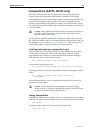
■ “CompactFlash (AR725, AR745 only)” on page 41
■ “SFP Ports (AR770S only)” on page 46
■ “PICs and NSMs” on page 46
■ “PCI Accelerator Cards (PACs)” on page 47
AR740 RPS Redundant Power Supply
(AT-AR725, AT-AR745 only)
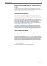
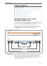
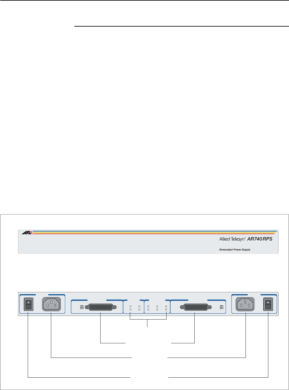
Each AR740 RPS can provide power supply and mains circuit redundancy for
up to two AC routers. The AR740 RPS cannot be used with DC versions of the
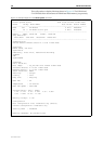
routers. Figure 17 shows the AR740 RPS front and rear panels.
Installation instructions for the AR740 RPS can be found in the AR740 RPS
Quick Install Guide. This guide is packed with each AR740 RPS, or can be
downloaded from www.alliedtelesis.com/support/software/ .
Figure 17: Front and rear panels of the AR740 RPS
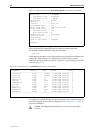
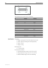
DC supply cables Two DC supply cables are packed with each AR740 RPS. If making your own
cable, use a cable that conforms to UL2464, and has at least twenty-three
24 AWG cores. The cables will need a DB25 male connector on both ends and
should be wired in a straight-through configuration. Pin outs for the
connectors are listed in Table 6.
Front panel
Rear panel
AC power
supply switches
AC power
supply inlets
LEDs
DC power outlets
(DB25s)
RPS DC OUTPUT 1 RPS RPS DC OUTPUT 2
AC POWER 1 AC POWER 2
AC Power
On
RPS Fan
Faul t
Main PSU
Faul t
RPS PSU
Faul t
Main Fan
Faul t
1
2
ROUTER
AC Power
100-240 VAC
50-60Hz
1.5A
AC Power
100-240 VAC
50-60Hz
1.5A
5V/6.5A
12V/1.0A
-12V/0.2A
5V/6.5A
12V/1.0A
-12V/0.2A