


Hardware Reference 7
C613-03087-00 Rev E
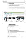
Asynchronous Ports The two asynchronous serial ports can be used as general purpose ports for
terminals, printers, or modems. They are effectively identical and can be
independently configured. The default communications settings are:
• 9600 bps
• 8 data bits
•1 stop bit
•No parity
• Hardware flow control
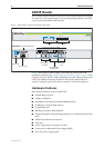
PIC Bays The chassis has two Port Interface Card (PIC) bays, which can accommodate any
combination of the following PICs:
■ AT-AR020 PRI E1/T1 PIC, one primary rate E1/T1 port
■ AT-AR021(S) BRI-S/T PIC, one basic rate ISDN S/T port
■ AT-AR021(U) BRI-U PIC, one basic rate ISDN U port
■ AT-AR022 ETH PIC, one Ethernet LAN AUI/10BASE-T port
■ AT-AR023 SYN PIC, one synchronous port with universal 50-way
AMPLIMITE connector
■ AT-AR024 ASYN4 PIC, four asynchronous ports with R-J45 connectors
■ AT-AR026 4ETH PIC, four 10BASE-T/100BASE-TX ports with RJ-45
connectors
■ AT-AR027 VoIP-FXS PIC, two Foreign Exchange Subscriber (FXS) ports
with RJ-11 connectors
CompactFlash slot The AT-AR725 has a CompactFlash slot on its front panel. For information on
CompactFlash, including a list of compatible flash cards, see “CompactFlash
(AR725, AR745 only)” on page 41.
PAC slot The AT-AR725 router has a single PAC slot inside the chassis. When installed,
PACs provide hardware-based encryption and or compression capability via a
PCI interface. For information on PACs, including a list of compatible PACs,
see “PCI Accelerator Cards (PACs)” on page 47.
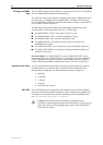
Power Supply
The AT-AR725 is available in two power supply configurations: a universal AC
model and a 48V DC model. The AC model includes an inlet for the AR740 RPS
(Redundant Power Supply). The AR740 RPS can be purchased separately, and
each unit supports up to two AT-AR725 or AT-AR745 routers.
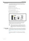
AT-AR725 AC AC models of the AT-AR725 have a universal AC input connector and a power
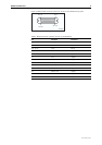
switch on their rear panels. A DB25 connector for an optional external
Redundant Power Supply (RPS), such as the AR740 RPS, is also located on the
rear panel.
Pin outs for the DB25 RPS connector, and cable specifications for RPS supply
cables, can be found in “Redundant Power Supply (RPS)” on page 8.
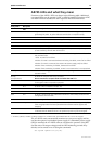
The router can monitor the PSU and the fan in both the router and the RPS. See
“AR725 LEDs and what they mean” on page 10 for more information.