


56 AR700 Series Router
C613-03087-00 Rev E
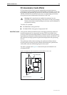
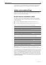
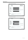
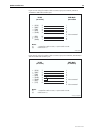
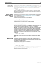
Figure 29: Pin wiring diagram for a Macintosh serial cable to connect asyn port on AR725,
AR745 or AT-AR024 to MiniDin (Macintosh)
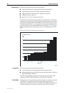
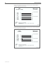
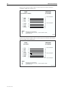
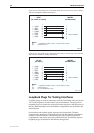
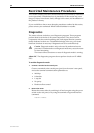
Figure 30: Pin wiring diagram for a Macintosh serial cable to connect asyn port on AR750S,
AR750S-DP, or AR770S to MiniDin (Macintosh)
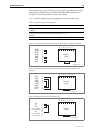
Loopback Plugs for Testing Interfaces
Loopback plugs are used in conjunction with the Test Facility software (see the
Test Facility chapter) to test the router’s physical interfaces. The purpose of a
loopback plug is to connect the output pins on the interface to the input pins so
that any data transmitted over the interface is looped back and received at the
same interface.
On interfaces with control signals, these are also looped back. The data
received on the interface is compared with the data transmitted to determine
whether or not the interface is functioning correctly. In order to produce a
comprehensive test report, most tests performed by the Test Facility require a
loopback plug to be inserted in the interface being tested.
RJ45
(to switch or router)
MiniDin
(to Macintosh)
1
2
3
4
5
6
7
8
←
→
←
→
→
←
→
(DCD)
(RTS)
(RXD)
(GND)
(TXD)
(CTS)
(DTR)
Not connected
Notes:
(1) → Output from switch or router; ← Input to switch or router.
(2) Cable version 1.0.
MINIDIN
1
2
8
5
4
6
7
3
RJ-45
(to router)
MiniDin
(to Macintosh)
1
1
2
3
4
5
6
7
8
←
←
→
←
→
→
→
→
(DCD)
(CTS)
(RTS)
(RXD)
(GND)
(TXD)
(GND)
(DTR)
Not connected
Notes:
(1) → Output from switch or router; ← Input to switch or router.
(2) Cable version 1.0.
(3) Pin 1 on MiniDin has 2 wires.
minidin_ar750
7
8
1
6
4
3
5
2