


8 AR700 Series Router
C613-03087-00 Rev E
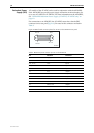
AT-AR725-80 DC The AT-AR725-80, designed for use by telecommunication carrier sites,
supports connection to a 48V DC power supply (in the range 39 to 60 V DC).
The DC model does not support an RPS connection, and does not support
monitoring of the main PSU or fan.
DC supply cable specifications:
■ Number of wires (cores): 3
■ Minimum size: 2.1 mm
2
(14 AWG)
■ Minimum cable rating: 600 V, 90 degrees Celsius
DC power supply specifications:
■ 48 V DC (38 V to 60 V DC is acceptable)
■ Either positive grounded or negative grounded
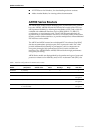
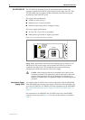
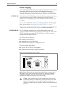
Figure 2: DC Power inlet terminals on an AR725
Safety Safety information and instructions outlining how to connect an AT-
AR725-80 to a DC power supply can be found in the AR700 Series Router
Installation and Safety Guide. You should read these instructions before
attempting to connect the router to a DC power supply.
!
Caution Some interfaces that may be installed in the router are not
transformer isolated. This means they will be referenced to the frame
ground of the equipment and may be damaged if connected to an
interface on another piece of equipment which is at a different ground
potential.
Redundant Power
Supply (RPS)
AC models of the AT-AR725 can be used in conjunction with the AR740 RPS.
Each AR740 RPS can provide power supply and mains circuit redundancy for
up to two AT-AR725s or AT-AR745s. For more information on the AR740 RPS,
see “AR740 RPS Redundant Power Supply (AT-AR725, AT-AR745 only)” on
page 43.
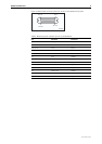
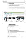
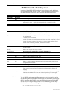
For connection to an AR740 RPS, the AT-AR725 router has a female DB25
connector on its rear panel (Figure 3). Pin outs for the connector are listed in
Table 2.
3
1
FOR CENTRALIZED DC
POWER CONNECTION,
INSTALL ONLY IN A
RESTRICTED AREA
38-60 VDC , 2 A
DC POWER