ADVANCED MICRO SYSTEMS, INC. HARDWARE
7
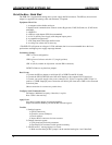
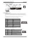
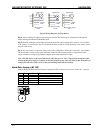
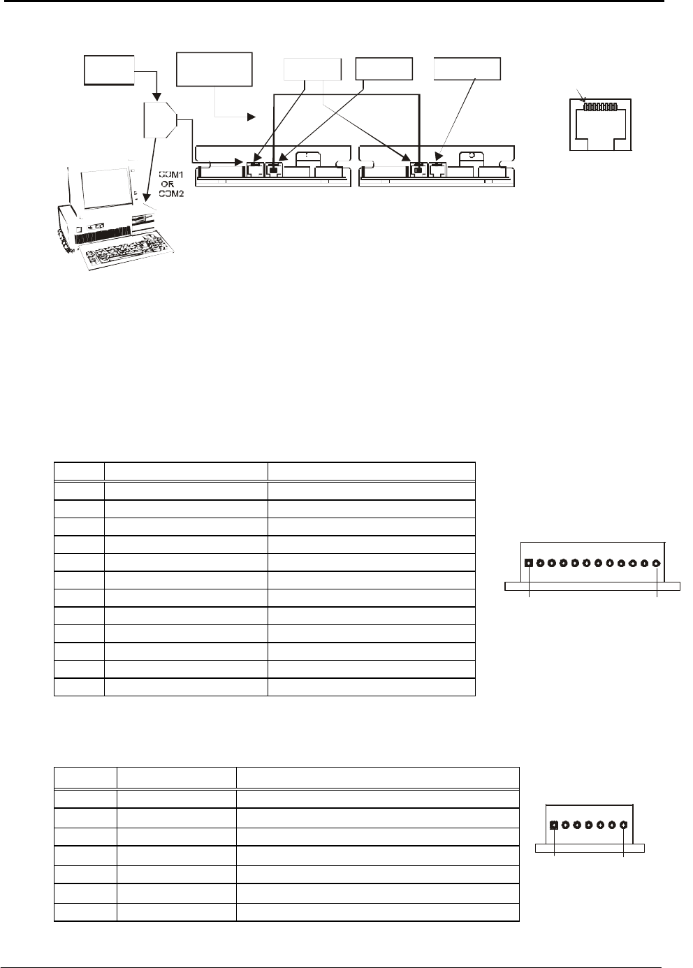
Multi-axis Serial Interface Connection
DCB-274 #1 DCB-274 #”N”
SERIAL
INTERFACE
ADAPTER
SIN-8
OR
SIN-10
BLC-51-XX
INTERCONNECT
CABLE
SERIAL IN SERIAL OUT
TERMINATOR
PLUG
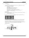
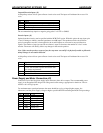
I.O. Connections (J1, J4)
The DCB-274 has a robust set of input and output signals. Two connectors (J1 and J4) provide dedicated
inputs and outputs. Five user-defined signals are also provided. All inputs can withstand voltages in
excess of +28 volts. Two high-voltage, high-current outputs are available to drive solenoids, relays, motors,
etc.
Fourteen input signals can be configured as either sourcing or “PLC” inputs. Thus, many
controllers/sensors that provide “true” outputs are easily adaptable.
(J1)
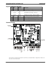
Pin Signal Description
1 Port 1 Input
2 Port 2 Input
3 Port 3 Input
4 Port 4 Configurable output or input
5 Port 5 Output
6 Gnd Power common
7 +5v Vcc – logic power
8 Jog-1 Input
9 Jog-Speed Input
10 Jog-2 Input
11 Step or Encoder A Input
12 Direction or Encoder B Input
Note: Outputs are 5-volt logic with 10k pull up to 5 volts.
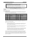
(J4)
J4 Pin Signal Description
1 Home input Used with the F[ind] home command
2 Limit A input Inhibits motion in + direction only
3 Limit B input Inhibits motion in - direction only
4 Go input Start stored program sequence at location 0
5 Soft Stop input Stop stored program sequence
6 Gnd System power common
7 VIO +4.5 volts out or VIO input
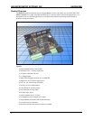
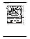
P
i
n
1
J4
P
i
n
7
P
i
n
1
J1
P
i
n
1
2
J2, J3
Pin 1


