


ADVANCED MICRO SYSTEMS, INC. SMC-27X2 SOFTWARE
39
If “t” is a one, the TRACE mode is turned on. A display of the current step being executed is produced while
the program is running. The list format is the same as that of the “Q” command The TRACE mode will be in
effect until the program execution terminates or until an embedded ‘Go’ without the trace attribute is
encountered.
The address range is 2047, depending on NV memory capacity. Address locations between 225 and 255 are
reserved for parameter storage and may not be used in programs. The SMC-27X2 also features a special
case for the “Go” instruction.
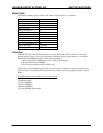
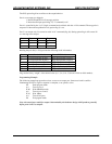
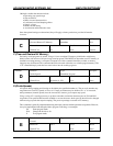
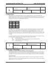
The controller is factory set with the following program example:
P 0 Enter program mode.
+ 1001 Move 1001 steps in the plus direction.
W 100 Wait 100 milliseconds.
- 1000 Move 1000 steps in the minus direction.
W 100 Wait 100 milliseconds.
Z 0 Display step position.
G 0 0 Go to location 0 and run stored program.
P Exit program mode.
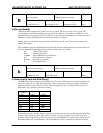
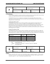
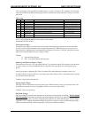
Special case “Go”
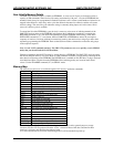
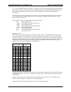
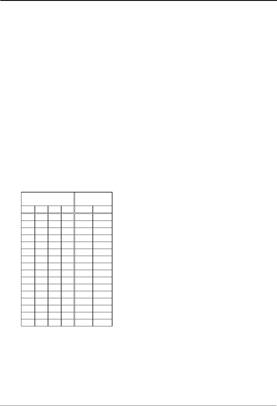
If the address is specified as 2048 (above the last NV memory address), the SMC-27X2 will read the input
ports, then, branch to an address based on the state of input ports 1 through 4. In such case, each state of
the input ports acts as a “go switch.” To prevent any confusion to the controller, each address should have
a program associated with it even if it is simply “G 2048 0” to go back into the “branch to mode.” The target
address starts at the second page of program memory, starting at address 256 with 16 character (byte)
intervals. This instruction is analogous to “on PORT go to.”
Input Port State:
Address of
“Go -to”:
P1 P2
P3
P4 HEX
1 1 1 1 0 256
0 1 1 1 1 272
1 0 1 1 2 288
0 0 1 1 3 304
1 1 0 1 4 320
0 1 0 1 5 336
1 0 0 1 6 352
0 0 0 1 7 368
1 1 1 0 8 384
0 1 1 0 9 400
1 0 1 0 A 416
0 0 1 0 B 432
1 1 0 0 C 448
0 1 0 0 D 464
1 0 0 0 E 480
0 0 0 0 F 496
The physical input ports are internally inverted as part of the address computation. When the PLC jumper is
in the STD mode (pins 1 and 2) a low is defined as a voltage above ½ VIO (no connect). A high is less than
½ VIO (GND).
When the PLC jumper is in the PLC mode (pins 2 and 3) the inputs are inverted. A low is defined as zero
volts (no connect), a high is a voltage above ½ VIO mode jumper.
Commands located in address space between 129-191 will execute much faster.