ADVANCED MICRO SYSTEMS, INC. HARDWARE
12
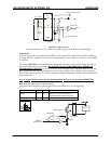
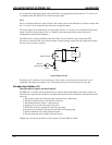
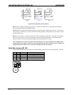
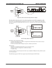
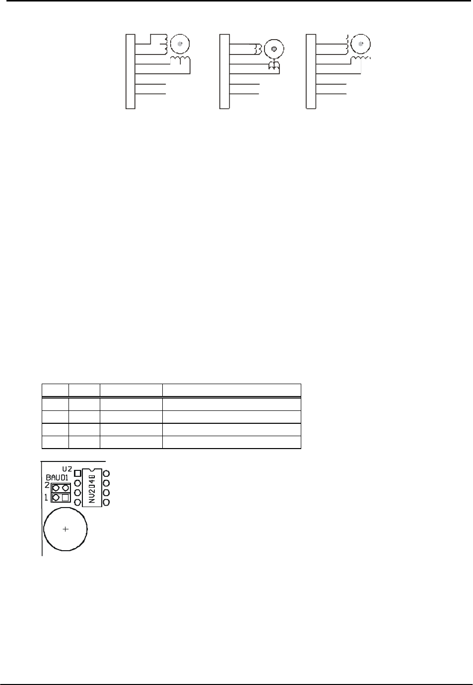
Typical Wiring Diagrams for Step Motors
Fig. A: Series winding for higher torque and lower current. The inductance is 4 times that of the parallel
mode, reducing the maximum obtainable speed.
Fig. B: Parallel winding for better high-speed performance but requires higher drive current. A 4-wire motor
is the same as an 8-wire motor, but it is connected (in either parallel or series) internally. Some motors can be
rewired at the factory.
Fig. C: A 6 wire motor is a variation of the 8 wire series configuration, where the “center taps” are available.
The 6-wire motor can be used in series mode but cannot be connected in parallel. A compromised 50%
copper connection can be used, producing higher speed with reduction of torque.
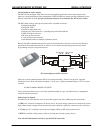
Note: NEVER connect or disconnect the motor when the power is “ON”. Wait at least two minutes after
turning off the power before connecting or disconnecting the motor. This will allow proper dissipation of
voltage from the unit. Failure to do so may cause damage and void the warranty.
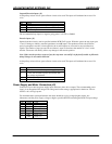
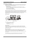
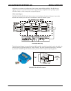
Baud Rate Jumpers (B1, B2)
Jumpers B1and B2 determine the baud rate. Standard UART properties are no parity, 8 data bits, 1 stop bit.
B1 B2 Baud Rate Comment
N N 9600 Factory setting N, 8, 1
Y N 460k Requires SIN-10 serial adapter
N Y 38.6k
Y Y 19.2k
+ Power
- GND
High Torque
+ Power
- GND
High Speed
Bipolar 50% Copper
Bipolar Series
FIG A
FIG C
+ Power
- GND
High Speed
PH-0
PH-1
PH-2
PH-3
VMM
GND
Bipolar Parallel
FIG B
6
5
4
3
2
1
6
5
4
3
2
1
6
5
4
3
2
1


