


ADVANCED MICRO SYSTEMS, INC. SMC-27X2 SOFTWARE
35
The PLC option flag 8 has no affect on the output behavior.
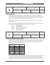
Port 4 as an output (as shipped):
1. Install JP1and JP2 in off (storage) position.
2. Insure that P4 input option flag 32 (“l” command) is off.
Port 4 is controlled by the “A 8” (flag 8) command and read back with the A 129 command. The step pulse is
output to P4 when the step/direction out (option flag 2) is set.
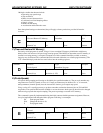
Port 5 is an output only. It is turned on with “A 16” command (flag 16). Setting option flag 4 will convert P4
to a moving status output.
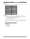
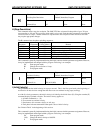
Port Flag Port Flag
1 1 4 8
2 2 5 16
3 4 129 Read Port
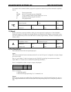
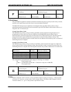
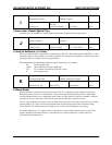
Reading the port data (A 129) provides the following result information:
Data Cause (Standard Mode) Cause (PLC Mode)
1 Low input present on port 1 High input present on port 1
2 Low input present on port 2 High input present on port 2
4 Low input present on port 3 High input present on port 3
8 Low input present on port 4 High input present on port 4
3 Low on ports 1 and 2 High on ports 1 and 2
15 Low on ports 1, 2, 3 and 4 High on ports 1, 2, 3 and 4
Flags are the binary “weight” of the decimal value (0, 1, 2, 4, 8, 16, 32, 64 and 128 for an 8-bit number).
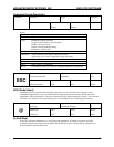
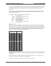
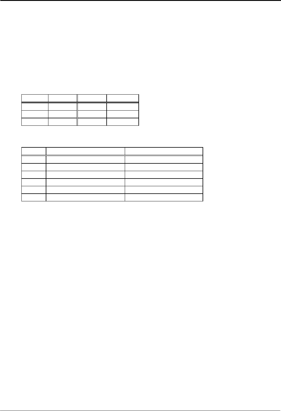
Programming Example
The following example program shows how to turn on an output port. Some uses for this could be
illuminating an LED to signal a sequence is complete, or to operate a valve.
P 0 Enter program mode.
A 4 Turn on port 3.
W 60 Wait 600milliseconds.
A 6 Turn on port 2 and 3.
W 10 Wait 100ms.
A 0 Turn off all ports.
P0 Exit program mode.
Note: the actual ports usable for output is determined by the hardware design. AMS products generally
define ports 4 and 5 as outputs.