ADVANCED MICRO SYSTEMS, INC. SERIAL INTERFACE
17
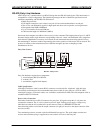
RS-422 (Party Line) Hardware
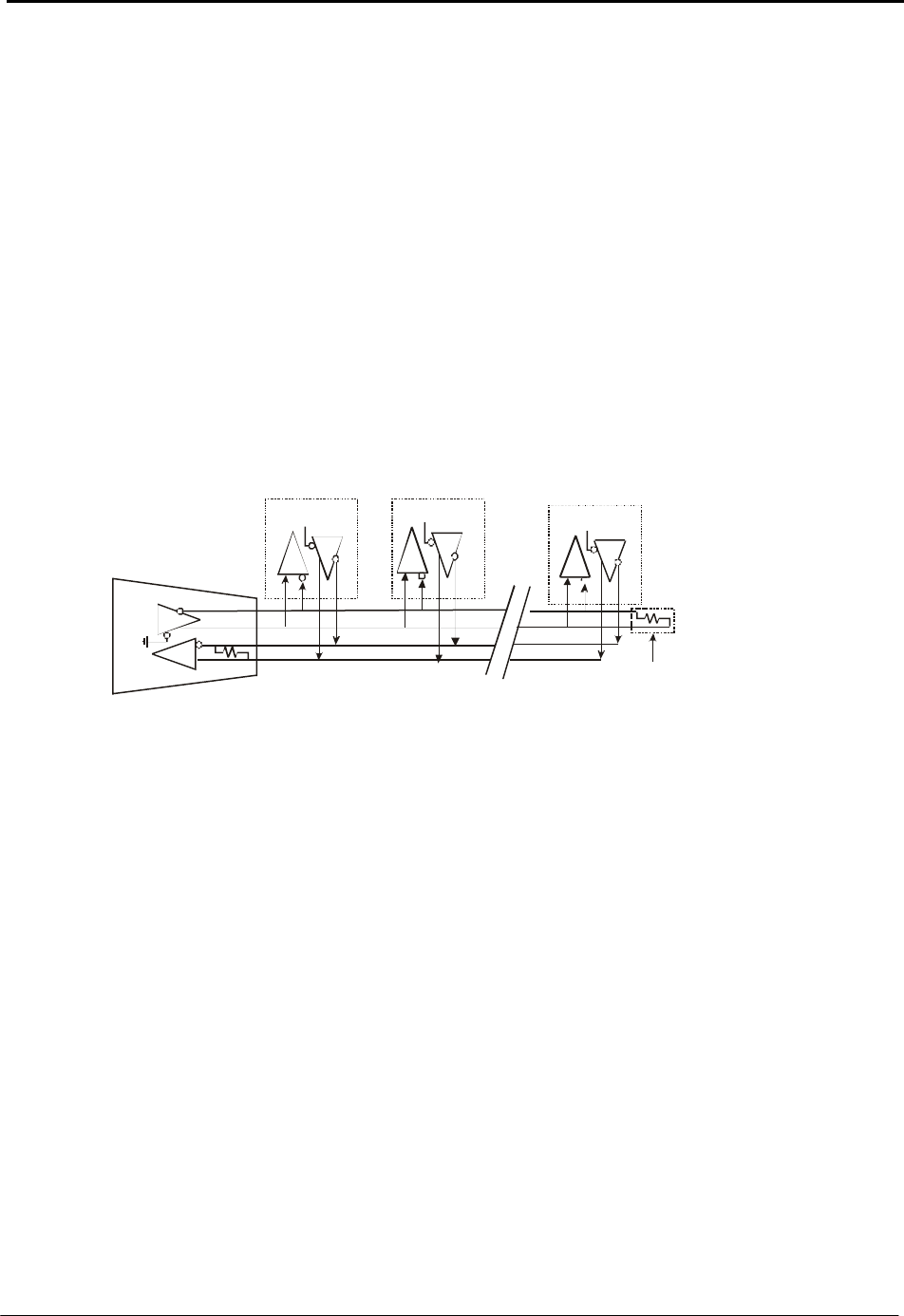
AMS “Party Line” communication is an RS-422 design that uses RS-485 rated circuits. This interconnect is
comparable to a LAN configuration. The hybrid design merges the best of both EIA specifications and
maintains compatibility with EIA RS-422 and features:
• Multi drop serial bus
• Full duplex connection; receive data is one pair of wires and transmitted data a second pair.
• Zero to five volt differential signals for high speed and robust noise rejection over long distances
• Data speeds from 100K to10M Baud
• Up to 32 controllers from one COM port
• Cable network length to 1200 Meters (4000 ft)
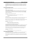
One master host computer can address a device (axis) with a command. The single packet of up to 15 ASCII
characters begins with a single character corresponding to the axis “name” and terminated with a single line-
feed character. Handshake is necessary and is based on each transmitted character being echoed. Prior to
the terminating LF character, numbers representing data such as position or limit status will be received. The
protocol is similar to other manufactures but is different enough to prevent co-mingling of other
manufactures devices.
Party Line Connect
RS-422 “Party Line”
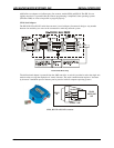
Party line hardware requires three components:
1. A serial adapter (RS-232 to RS-422),
2. A cable(s) and
3. A terminator (supplied with adapter).
Cable Specifications
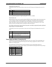
Although 8-conductor (with 8 contact RJ-45 connectors at each end) flat “telephone” cable has been
successfully used in the past, the recommended interconnect cable for party line use is UTP 24 AWG..
twisted pair (category 5) network cables, now available as standard from AMS. The older telephone cable is
suitable for RS-232 or lab work.
Device (Axis) Connection
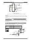
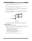
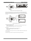
Each motor controller has two RJ-45 connectors for party line. All signals except the +5 volt power are
connected in common. The +5 volt is isolated to prevent “back” feeding power supply voltage to any
individual axis with the AC switched off or power removed. Thus, it is IMPORTANT that the
interconnecting cables travel from the output connector (on right) of one axis to the input connector of the
next axis (on left).
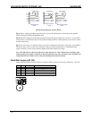
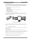
Two terminating resistors are used on the last differential line receiver. The serial adapter contains one
resistor and a terminator plug is supplied to be used on the LAST axis in the Party bus.
AXIS A AXIS B
AXIS “n”
SERIAL ADAPTER
C
O
M
P
U
T
E
R
TERMINATOR


