


ADVANCED MICRO SYSTEMS, INC. HARDWARE
3
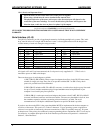
Required Hardware for Operation
Qty Unit Model # Description
1 Axis DCB-274 Driver-Controller Board
1 System User defined +24 to 40Vdc power supply
1 Axis SIN-7 RS-232 serial adapter (single axis)
or
1 System SIN-8 RS232/RS422 serial adapter (multi-axis)
or
1 System SIN-10 Intelligent serial adapter (Windows 2000/NT)
1 Axis BLC-38 7 pin home/limit mating connector (included)
1 Axis BLC-44 6 pin mating motor connector (included)
1 Axis BLC-50 12 pin mating I.O. connector (included)
1 Added axis BLC-51-3 Interconnect cable, Cat5 (3 ft.)
1 System TERM-2 Terminator plug (included with SIN-8 or SIN-10)
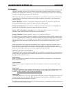
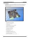
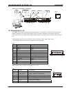
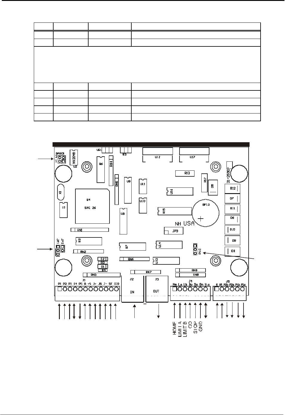
Assembly Drawing
Unless otherwise specified clamp diodes D-1 and D-2 are not installed. Refer to “Output Ports” further on in
this section for more information.
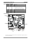
BAUD RATE
SELECT
SERIAL
IN
SERIAL
OUT
P1
P2
P3
P4
P5
GND
+5V
JOG 2
JOG S
JOG 1
STEP/ENC. A
DIR./ENC. B
P
H
2
B
P
H
2
A
P
H
1
B
P
H
1
A
MOTOR
GND
+24-40 VDC
V
I
O
PORT 4
CONFIGURE
PLC MODE
CONFIGURE