


ADVANCED MICRO SYSTEMS, INC. HARDWARE
8
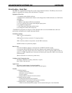
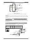
Pin 7 - VIO Reference Input
This signal defines the input and output voltage range. A “default” voltage of 4.6 volts is derived from the
internal +5-volt supply, via a diode. Any external load must be limited to several mA. You may apply an
external, higher “VIO” voltage, if appropriate to the application. The input signal thresholds will be
approximately ½ of VIO or 2.3 volts. The threshold is the same, independent of PLC or “normal” mode.
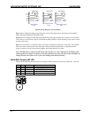
Input Ports
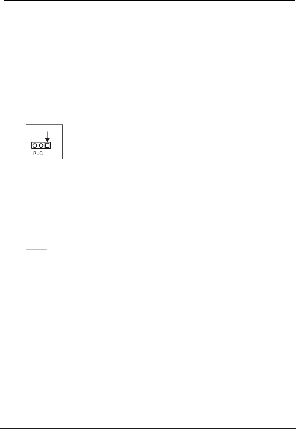
All inputs incorporate 10k resistors that may be set as pull-up to the VIO voltage or pull-down to ground as
defined by the three-pin “PLC” jumper. When the jumper is in the “PLC” position, (pins 2 and 3 installed)
the resistors pull-down and maintain a zero volt level on the inputs. All these inputs will withstand 28 volts
DC, even if a lower VIO voltage is used. The possible inputs include; (J1)- ports P1, P2, P3 and P4
(selectable), Jogs (3), Step and Direction and (J4)- Home, Limits (2), Go, and Soft Stop. VIO becomes
especially important where outputs drive high voltage devices.
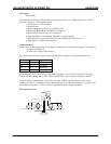
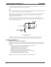
Standard Mode- Sinking Inputs
When the PLC jumper is in the standard mode position (pins 1and 2 installed) the resistors act as pull-up to
the VIO supply. Depending on your mode, software commands to invert the signals using the ”l” (lower
case L) command may be required for proper operation.
In the “standard” mode, the 10k pull-up resistor will become a pull-down resistor as the input signal exceeds
4.6 volts. When the voltage does exceeds 4.6 volts it will cause a pull-down affect because of the internal
resistance divider.
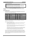
Example
When 28 volts is applied to an input, the drive current will be about 0.7 mA per signal. The threshold
voltage will increase as each 28-volt signal is applied, approaching 8.5 volts when all are high. The preferred
input drive method is open collector (drain) transistor or switch to common (GND).
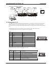
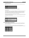
PLC Mode- Sourcing Inputs
When PLC jumpers (pins 2 and 3) are installed, the pull-up resistors are transformed to pull-down resistors.
Activating an input is accomplished by asserting a voltage exceeding ½ VIO on the given input. When
these inputs are held low, the logic sense is inverted. For proper operation a mode command must be
entered and stored in NV memory. Use the “l” (lower case L) command to configure the inputs. The “l 9”
command will invert all of the inputs. The “l 8” command will invert all but the limit switch inputs.
The “l” command defines several configurations. Please refer to the command section for details. These
inputs can withstand in excess of 28 volts. The default threshold will remain at 2.3 volts unless an external
VIO is supplied.
A higher VIO (i.e., 24 volts from a PLC with 24 volt drivers) would increase the logic threshold to 12 volts,
providing better noise immunity.
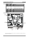
PIN 1