


Wiring and Device Connections
12
TPI-PRO Total Presentation Interface - Pro Edition
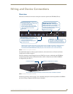
System Diagrams
The following System Diagrams illustrate the most common applications for the TPI-PRO. For detailed
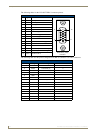
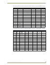
pinout descriptions for each connector on the TPI-PRO, refer to the
Connector Details and Pinout
Configurations section on page 17.
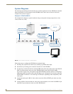
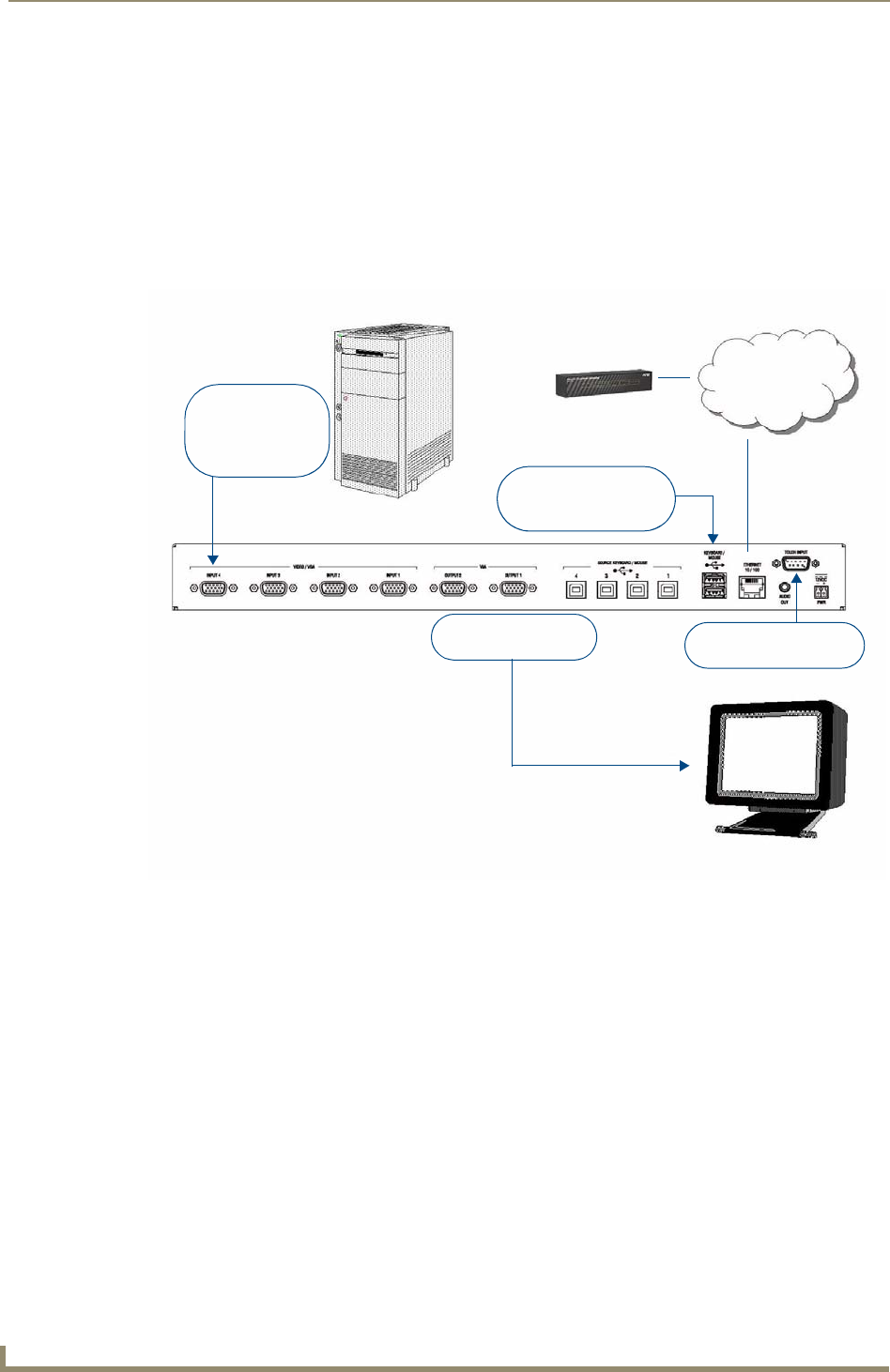
Example 1 (TOUCH INPUT)
The example below displays a typical installation using a touch panel to display output from a video
source (in this case, a PC.)
Follow these steps to configure the TPI-PRO for touch panel input:
1. Discharge any acquired static electricity by touching a grounded metal object.
2. Disconnect any incoming power connector from the rear of the TPI-PRO.
3. If connecting a serial touch monitor, attach the DB9 touch panel cable (male) to the 9-pin TOUCH
INPUT connector (male) on the rear of the TPI-PRO. Refer to the
TOUCH INPUT (DB9)
Port section on page 21 for a description of the TOUCH INPUT connector pinouts. If connecting a
USB touch monitor, attach the cable to the USB Type A port. Touch panels can connect to either the
TOUCH INPUT connector or one of the Type-A USB ports, depending on the compatibility of the
touch panel.
4. Connect the touch panel’s HD-15 video cable to one of the VGA OUTPUT port on the rear of the
TPI-PRO.
5. Connect an HD-15 cable from the rear video port (on the computer) to one of the VGA/RGB 15-pin
male HD-15 input connectors on the rear of the TPI-PRO unit.
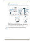
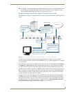
FIG. 8 System Installation Example 1 (TOUCH INPUT)
Ethernet
NetLinx Master
PC
Touch Panel
Signal video feed
from the computer
to the touch panel
through the
TPI-PRO.
Connect VGA Output
to touch panel
Serial touch input
from serial touch panel.
USB-compatible touch
panel connected to
Type-A USB port.