


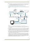


Wiring and Device Connections
23
TPI-PRO Total Presentation Interface - Pro Edition
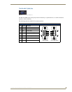
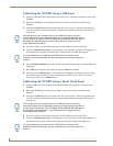
Power (2-Pin Captive Wire) Connector
The TPI-PRO requires a 12 VDC-compliant power supply to provide power to the TPI-PRO via the
2-pin 3.5 mm mini-Phoenix PWR connector. The incoming PWR and GND wires from the power supply
must be connected to the corresponding locations within the PWR connector.
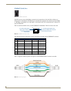
To use the 2-pin 3.5 mm mini-Phoenix connector for use with a 12 VDC-compliant power supply, the
incoming PWR and GND wires from the external source must be connected to their corresponding
locations on the connector (
FIG. 19).
1. Strip 0.25 inch (6.35 mm) of insulation off all wires.
2. Insert the PWR and GND wires on the terminal end of the 2-pin 3.5 mm mini-Phoenix cable. Match
the wiring locations of the +/- on both the power supply and the terminal connector.
3. Tighten the clamp to secure the two wires. Do not tighten the screws excessively; doing so may strip
the threads and damage the connector.
4. Verify the connection of the 2-pin 3.5 mm mini-Phoenix to the external 12 VDC-compliant power
supply.
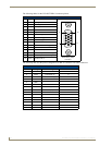
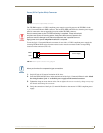
FIG. 18 Power (2-Pin Captive Wire) Connector
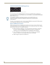
Do not connect power to the TPI-PRO until wiring is complete. These units should
only have one source of incoming power. Using more than source of power to the
panel can result in damage to the internal components and a possible burn out.
Apply power to the panels only after installation is complete.
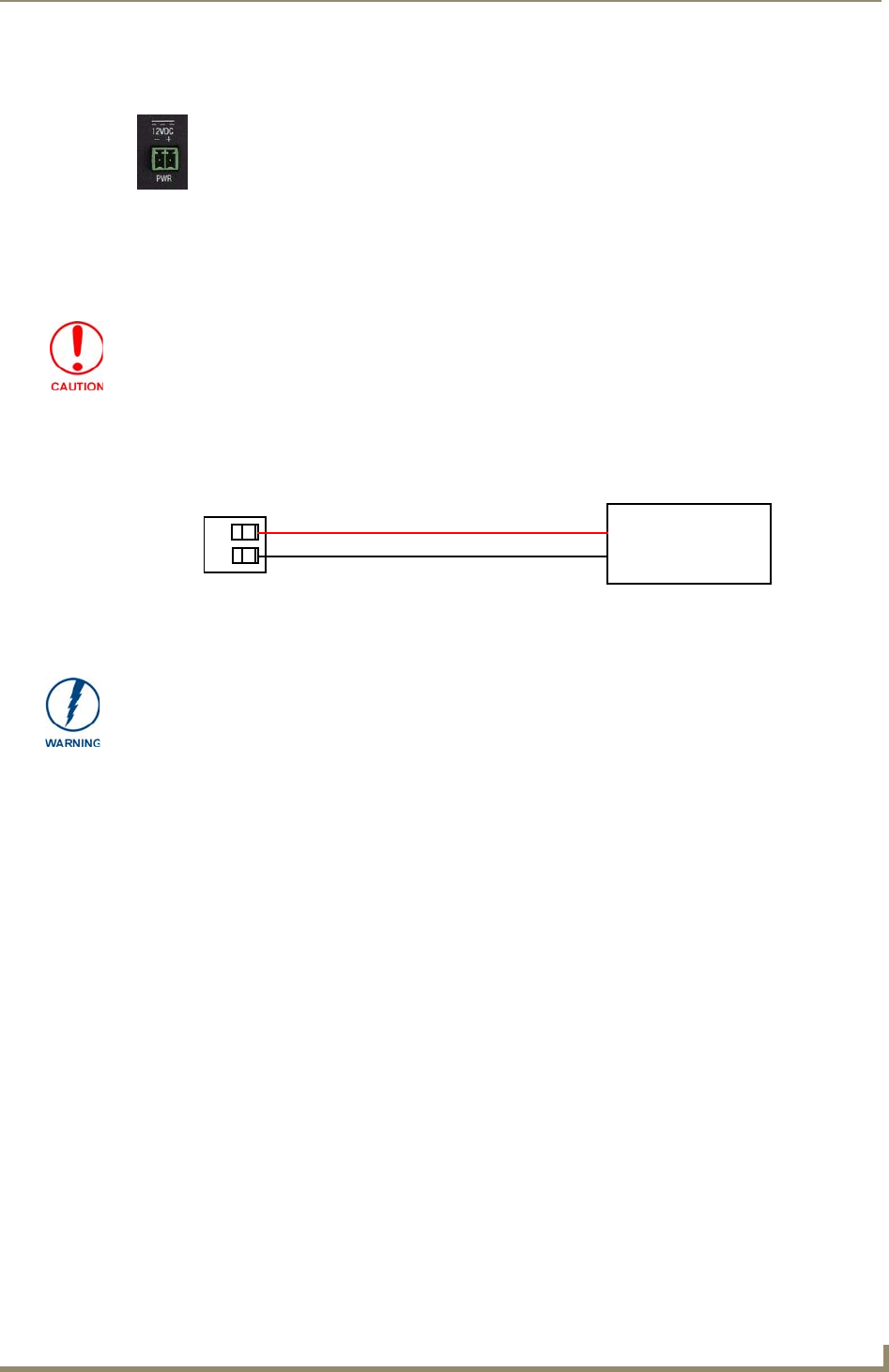
FIG. 19 NetLinx power connector wiring diagram
PWR +
GND -
To the TPI-PRO
Power Supply
Never pre-tin wires for compression-type connections.