


2.14 INSTALLATION
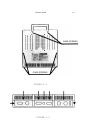
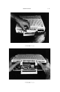
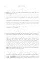
8. Pull off the speaker ConnecTOR from the speaker pins underneath the
connector. The speaker connector is identified in Figure 2.8.
9. Remove the CPU and MMU from the motherboard. These components are
identified in Figure 2.8.
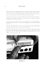
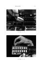
Using a small metal spoon, as Figure 2.10 shows, insert the bowl and of the
spoon between the CPU and MMU and their respective sockets. Rock the spoon
back and forth to loosen the component from the socket at one end. Repeat
this on the other end until the components are loose enough to remove by
hand.
Alternately, you may use a knife or small screwdriver to pry up the chips
if a spoon with a small enough lip is not available.
Be careful when removing the CPU and MMU that you do not accidently hand
their pins. If you do accidently bend a pin, carefully use a small needle
nose plier to straighten out the pin.
Plate the removed CPU and MMU on the soft cloth.
Disassembly is now complete.
Preparing The Card
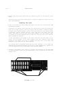
1. Insert the removed CPU and MMU into the MultiRam C Card. As Figure 2.8
shows, the CPU should be inserted into the lower socket and the MMU the
upper socket, just as they are located on the motherboard.
To insert the components, line up the pins of the CPU and MMU with their
respective sockets holes on the card. The notch on both components should
face to the left towards the RAN on the card. Insert one aide of the
components pins slightly into the socket. Then, using an inward
pushing/rocking motion, seat the pins on the other aide of the component.
If the pins do not easily seat, you may need to very slightly bend all pins
on one side of the component inward. Place the component on the table on
its side. Lift the component slightly up so that pressure can be
uniformily applied to all pins along one side. Apply firm, even, gradually
increasing pressure until some small inward movement in the pins is
detected. Do not apply too much pressure or the pins will bend too far.
Repeat the procedure on the opposite side. Retry inserting the component.
Repeat this procedure again if the pins are still too far outside the
socket to he moved into the socket holes.
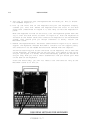
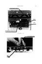
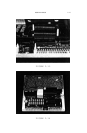
2. Insert the six keyboard support posts into the six holes on top of the
card. Insert the two longest posts into the holes at the top left corner
and center of the card as Figures 2.11 and 2.12 show. Insert the four
short posts into the four remaining holes on the card. Do not change the
position of the four short pins which are on the bottom aide of the board.
Insert the end of each pin with the longer collar into the holes. You can
insert the end with the shorter collar into the holes but the pin will be
harder to remove later it the pin must be removed for any reason.