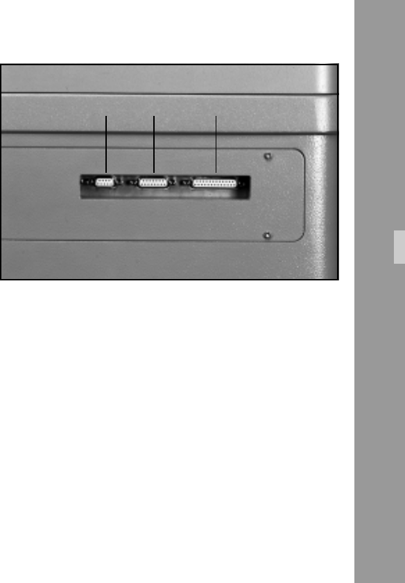
X1X2X3
43
6.9 Interfaces
Note: All interface cables used must comply with CE
and EMV guide lines.
6.9.1 Serial Interface (X1)
Plug type: Sub-D 25 pin socket
Via serial interface (X1) ➪ photo the operational status of the
LOCPRO 35 can be checked and changed from a computer.
Chapter 8 ”Serial Interfaces X1” contains listings of
technical data as well as listings of computer commands.
Plug – Pin configuration: See Annex ”Interfaces”
6.9.2 Ext Synchro (X2)
Plug type: Sub-D 15 pin socket
Via this interface ➪ photo a signal for shutter synchroni-
zation can be supplied externally and the internal shutter
signal accessed.
Cine Mode: ........................................................ 48 Hz
Normal and Telecine Mode: ....................... 50 or 60 Hz
Shutter revolutions can be changed by ± 3%.
Input: .................... 5 V TTL potential-free on optocoupler
Output: ................. 4 V potential output or potential-free
Plug Pin configuration: see annex ”Interface”
Note for shutter synchronization:
Signal source:
External = control frequency via X2; top priority!
Video = when video ”on”. Quartz of video camera.
Internal = internal quartz generator.
Functions


