


6
OmniViewIP 5216K/5232K
SECTIONSTable of Contents 2 3 4 5
6
1
INTRODUCTION
Unit Display Diagrams
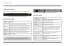
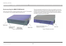
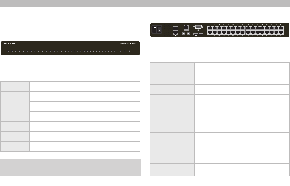
Figure 1 illustrates the front panel of the OmniView IP 5232K Switch.
Lj\i)Lj\i(
GFN<I
(''$)+'M8:,'&-'?q
CF:8CLJ<I
MD(
J<I@8C(
J
<
I
)
MD)
GFN<I
(''$)+'M8:,'&-'?q
Digital
Analog
Lj\i)Lj\i(
GFN<I
(''$)+'M8:,'&-'?q
CF:8CLJ<I
MD(
J<I@8C(
J
<
I
)
MD)
GFN<I
(''$)+'M8:,'&-'?q
Digital
Analog
Figure 1 OmniView IP 5232K Switch – front view
LED and button table
LED Function
Port
Solid: Server is connected to and powered on
Fast Blink: When a port is being accessed remotely
Slow Blink: When a port is being accessed locally
Ready Solid Green: When unit is available for use
Link Blinking Green: Unit is connected to the network
Power Power Indicator
Figure 2 OmniView IP 5232K Switch – rear view
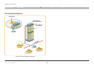
Connector table
Connector Function
Local Console
Connect a keyboard, video, and mouse to
operate the Switch locally.
Serial 1 Connect any serial device.
Serial 2 Connect any serial device.
LAN
Connect to 10/100Mb Ethernet. Yellow LED
illuminates when connected to a LAN. Green
LED illuminates when a remote session is
in progress.
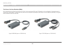
Server Ports
Connect to servers via SIMs (Server
Interface Modules).
VM1
Connect to server on server port 1 via
USB cable.
VM2
Connect to server on server port 2 via
USB cable.
Note: The port LEDs flash in series during boot up and during
systemupgrades.Allowapproximately45secondsforbootup.