


1716
INSTALLATIONINSTALLATION
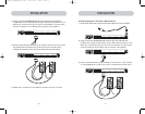
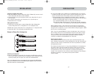
Connecting the Daisy-Chain Cable:
5. Begin with BANK 00. Using the Daisy-Chain Cable (F1D9402-XX), connect one end
to the “Daisy-Chain OUT” port on the first Switch.
6. Connect the other end of the Daisy-Chain Cable to the “Daisy-Chain IN” port of
the next Switch.
Note: It does not matter which unit is the primary unit, only that they are
connected OUT-to-IN or IN-to-OUT.
Adding Additional Units:
7. Continuing in the same manner, using the Daisy-Chain Cable (F1D9402-XX),
connect “Daisy-Chain OUT” to “Daisy-Chain IN” on all subsequent units.
CAUTION: Never connect “Daisy-Chain IN” to “Daisy-Chain IN” or “Daisy-Chain OUT”
to “Daisy Chain OUT”. This may produce unpredictable results.
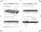
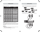
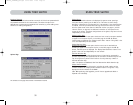
Example of Daisy-Chain Configuration
Connecting the Computers:
8. Power on the Switches, in any order. You will see the port LEDs flash on and off
and the seven-segment LEDs will light up, displaying a series of diagnostic codes,
eventually stopping with the digits “XX”, where XX is its BANK address.
Note: If the Switches still do not enumerate with their corresponding BANK address,
check that all Switches have the correct BANK address assigned to them and that all
daisy-chain cables are connected properly.
9. If the primary BANK is set to address 00, the KVM administrator must configure
the Switch for daisy-chain usage. To do this, take the following steps: (Note: You
may see lines across some of the consoles, which is normal since it is in an
invalid configuration until the “Daisy-Chain this Switch” option is activated).
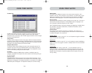
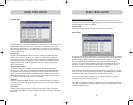
a) Open the OSD by pressing the CTRL key twice, then the space bar, and enter Setup.
b) Go to the Options page, select the “Advanced” button.
c) In the Advanced Dialog, check the “daisy-chain this KVM” box.
d) A dialog will appear informing you that, “This will reset the KVM to change this
setting.” Click “OK” to clear the dialog and automatically power cycle the Switch.
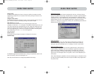
When the Switch reboots, it will interact with the remainder of the other daisy-
chained Switches as expected. You can verify this by opening the OSD and scrolling
through the list of computers; if any of the other Switch’s computers appear in BANK
00’s list, then it is working properly.
Note: If you don’t configure BANK 00 for use on the daisy-chain, then it will not be
able to interact with any of the other Switches and they will not be able to interact
with it. In addition, the unit’s front panel will not act the same as the other units’
front panels. Finally, there could be some unpredictable interactions caused by
connecting an improperly configured BANK 00 to a daisy-chain.
Powering Up the Systems
Once all cables have been connected, power up the connected computers in any
order. The Switch emulates both a mouse and keyboard on each port and allows your
computer to boot normally; the Switch does not need to be powered on to emulate
the keyboard and mouse.
The computer connected to port 01 of any primary KVM Switch will be displayed on
the monitor. Check to see that the Switch is working normally by use of mouse,
keyboard, hot keys, OSD, and/or front-panel push buttons. Proceed to do this with
all occupied ports to verify that all computers are connected and responding
correctly. If you encounter an error, check your cable connections for that computer
and reboot, if necessary. If the problem persists, please call Belkin
technical support.
Hosts 1 & 2 Hosts 3 & 4 Hosts 5 & 6 Hosts 7 & 8
Hosts 1 & 2 Hosts 3 & 4 Hosts 5 & 6 Hosts 7 & 8
Hosts 1 & 2 Hosts 3 & 4 Hosts 5 & 6 Hosts 7 & 8
Hosts 1 & 2 Hosts 3 & 4 Hosts 5 & 6 Hosts 7 & 8
P74290ea_F1DExxxC_man.qxd 30-10-2003 11:20 Page 16