


12 13
INSTALLATIONINSTALLATION
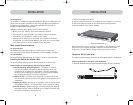
3. Connect the PS/2 or USB keyboard to the appropriate port on the back of the
Switch in the “Console” section (the purple PS/2 port).
4. Connect the PS/2 or USB mouse to the appropriate port on the back of the Switch
in the “Console” section (the green PS/2 port).
5. Repeat steps 1–4 above if you are connecting a second console.*
6. Power on the Switch.
7. Boot all of your host computers.
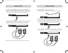
Connecting Multiple Switches (Daisy-Chaining)
You can daisy-chain up to 16 Switches and Expanders together; this will give a
server administrator control over a maximum of 256 computers. In addition, when a
second Switch is daisy-chained, two additional consoles can be added*, creating a
configuration of up to four consoles. Each daisy-chained group of Switches becomes
a unit that is referred to as a “BANK” and assigned an address. The Switch that the
console (keyboard, mouse, and monitor) is connected to is referred to as a “primary”
switch. BANKs 00 and 01 can be configured as primary console switches, allowing up
to four consoles. BANKs 02 through 15 can only be configured as secondary Switches
(without console support). If BANKs 00 through 01 do not have a console attached,
they function as secondary Switches. However, the connections on these BANKs are
hot swappable. For example, if a console is added to one of the first two BANKs, it
will immediately become a primary console Switch.
Note: A Daisy-Chain Cable (F1D9402-XX) is required to daisy-chain each OmniView KVM
Switch and is available through your Belkin reseller or online at http://www.belkin.com/
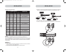
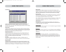
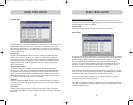
All OmniView ENTERPRISE Quad-Bus Series KVM Switches feature a “BANK DIP”
switch. The BANK DIP switch is used for proper identification of the Switch.
• For a single-unit configuration, set the BANK DIP switch on the Switch to the
“standalone” (BANK address 00) setting. This is the factory default setting.
• For multi-unit configuration, the BANK DIP switch on the primary units must be
set to BANK address 00 to (or) 01. Secondary units must be set to a unique
BANK address (from 02 through 15). Refer to the chart below for DIP switch
settings.
Note: BANK address 00 operates as standalone by default; refer to the section on the
OSD Options page for instructions on how to configure BANK 00 to join a daisy-chain.
*2x8 and 2x16 models only
4. Boot the computer you wish to connect via USB, as you would normally, with the
keyboard, mouse, and monitor connected directly to the computer.
5. Your computer will detect the Switch as a generic mouse and keyboard. Older
versions of Windows do not automatically install USB HID devices, so you will
have to manually press “Next” through the Windows Add/Remove Hardware Wizard
until the HID devices are all installed (the Switch will install four devices: a HID
keyboard, a HID mouse, a generic keyboard, and a generic mouse). This driver
installation is only required the first time the Switch enumerates on each
computer; the Switch will be detected and enumerate automatically in the future.
When driver installation is complete, power down the computer and disconnect
the keyboard, mouse, and monitor.
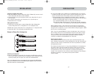
6. Connect the male VGA HDDB15 connector on the KVM Cable to the VGA port on
the computer.
7. Repeat steps 1 through 5 for each additional computer you wish to connect to
the Switch via USB.
Note: For USB Installation
We recommend you attach the KVM Cable directly to a free USB port on your computer,
not through a hub.
Connect the Console
1. Set BANK address (The BANK address is preset to zero at the factory).
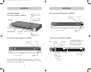
2. Connect the monitor to the Switch. Attach your monitor cable to the HDDB15
female port on the back of the Switch labelled “Console”.
NOTE: Dual-console support available on 2x8 and 2x16 models only.
Hosts 1 & 2 Hosts 3 & 4 Hosts 5 & 6 Hosts 7 & 8
P74290ea_F1DExxxC_man.qxd 30-10-2003 11:20 Page 12