


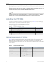

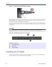
Installing the ET0100A
ETEP Installation Guide 37
NOTE
To meet the requirements of FCC Part 15 and the EU EMC Directive 2004/108/EC, use only shielded
cables with the ET0100A (DB-9 null modem cables and Category 5 STP cables).
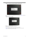
Unpacking the Shipping Carton: ET0100A
Remove all product components from the shipping carton and compare the contents to the packing list.
Keep all packaging in case it is necessary to return the unit.
The ET0100A is packaged with the standard items listed below. Additional cables, country-specific power
cords, and other accessories can be ordered separately.
1 ET0100A chassis
• Firmware and software is factory-installed on the unit.
2 Accessory Kit
• Rack mount kit containing two mounting brackets and 10 screws
• (1) Power cable (US)
• (1) Shielded DB-9 null modem cable (female to male)
• (1) Shielded Category 5 straight through cable (STP) with RJ-45 connector
• CD containing user documentation and a backup copy of the ETEP software
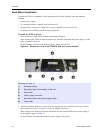
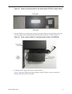
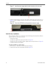
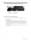
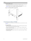
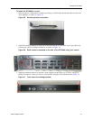
Rack-Mount Installation: ET0100A
The ET0100A can be mounted in a standard 19-inch rack using the mounting kit, or simply placed on a
rack shelf or solid surface. Before installing the ET0100A in a 19-inch rack, review the rack-mounting
guidelines listed in “ETEP Site Preparation” on page 28.
To mount the ETEP in a standard 19-inch equipment rack, have the following tools and materials
available:
• Two mounting brackets, supplied in the Accessory Kit
• (6) small screws and (4) large screws, supplied in the Accessory Kit
• #1 Phillips and #2 Phillips screwdrivers (user-supplied)
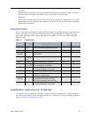
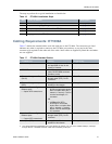
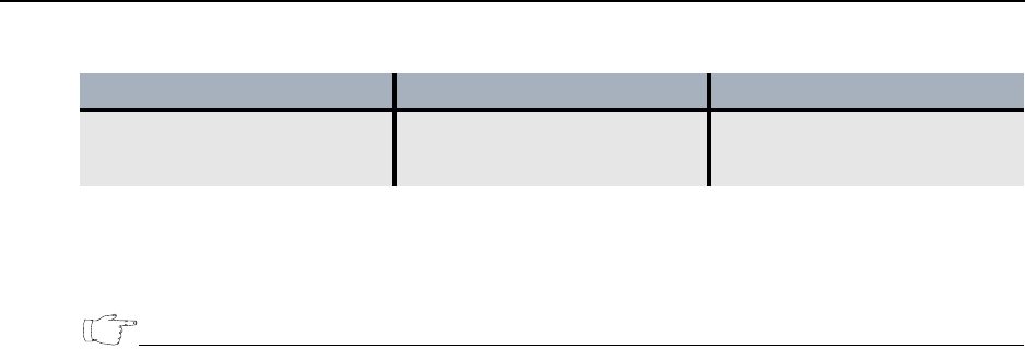
Remote and Local ports Shielded Category 5 straight
through cables (STP), RJ-45
connector
a
User
a. The local, remote, and Ethernet management ports are auto-sensing for polarity. You can use shielded Category 5
straight through cables or crossover cables when connecting to these ports.
Table 15 ET0100A Standard Cables
ET0100A Port Cabling Supplied by...