


Installing the ET10000A
ETEP Installation Guide 47
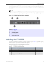
During the boot process the ET1000A cycles through its startup tests, and the corresponding diagnostic
codes are displayed. After the tests execute successfully, the diagnostic code display is solidly illuminated
with code 00.
NOTE
During the boot process the ET1000A discards all traffic on its data ports. Once the appliance is
operational, the default mode of operation passes all packets in the clear until you deploy security policies.
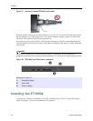
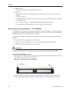
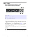
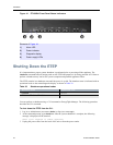
Figure 35 ET1000A Front Panel Status Indicators
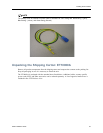
Installing the ET10000A
To prepare the ET10000A for installation, review the installation steps in Table 18, unpack the shipping
carton, and prepare a space for the installation of the appliance.
The steps to perform for a typical installation are listed below.
Elements of Figure 35:
1) Alarm LED
2) Diagnostic display
3) Power indicator
4) Power supply LEDs
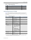
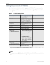
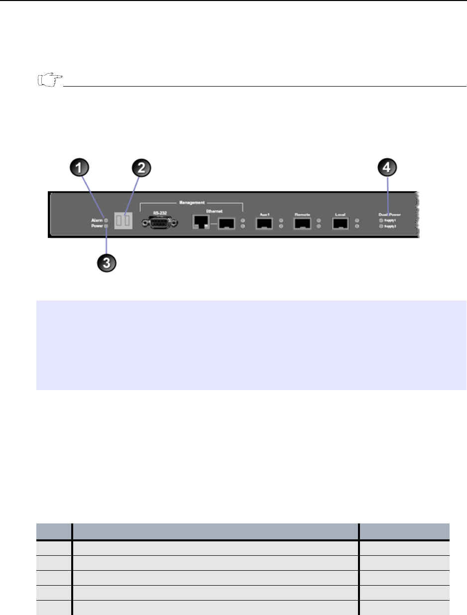
Table 18 ET10000A Installation Steps
Step Action to Perform Description
1 Review the cabling requirements. on page 48
1 Unpack the shipping package. on page 49
2 Prepare a space for installation of the ET10000A. on page 50
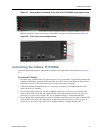
3 Connect the cables. on page 51
4 Apply power to the ET10000A. on page 52