


13
CHAPTER 2: Introduction
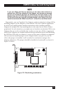
2.2 The Adapter Illustrated
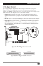
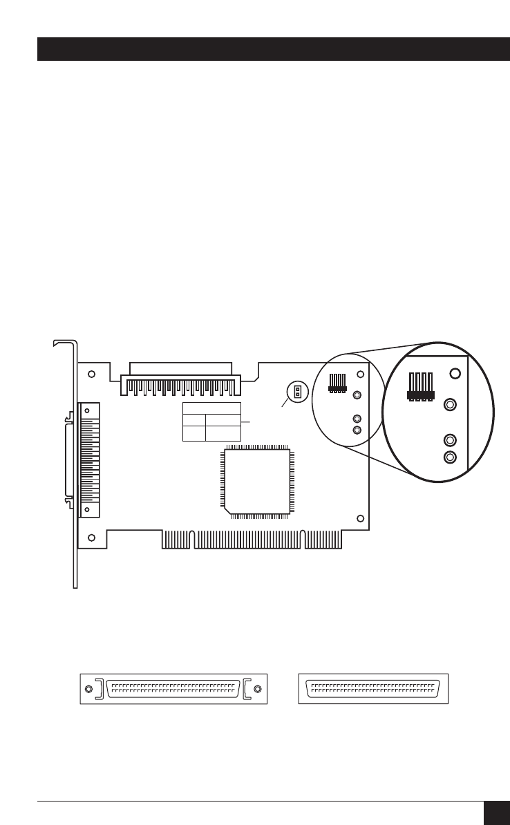
The Ultra2 LVD SCSI Host Adapter and its major components are shown in
Figure 2-1 below. You might want to refer to this diagram as you install your
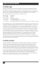
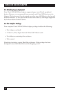
Adapter (see Chapter 4). Figure 2-2 below that shows closeups of the Adapter’s two
SCSI connectors. The Adapter’s other components include:
• Jumper JP1: These posts are usually left open so that termination can be
firmware-controlled. Put a jumper on them to hard-wire termination always
ON.
•
SE LED: Lights if any single-ended (legacy) devices are attached to the Adapter.
• LVD LED: Lights if any Ultra2 LVD SCSI devices are attached to the Adapter.
• ACT LED: Dark if the attached SCSI bus is passively terminated (which we
don’t recommend); lights if the bus is actively terminated (including forced-
perfect termination).
Figure 2-1. The Adapter’s circuit board.
Figure 2-2. The Adapter’s SCSI connectors.
SE LVD TERM ACT
VCC
LED
+
LED
–
VCC
14
SE LVD TERM ACT
VCC
LED
+
LED
–
VCC
14
JP1 TERMINATION
1–2
NO JMP SW CNTRL
<
Default
>
Always OFF
J6: Internal 68-Pin
Ultra2 Wide SCSI Connector
JP1:
Termination
Jumper
J1 (Internal)
J2 (External)
J4:
External
68-Pin
Ultra2 Wide
SCSI
Connector
J3:
LED
Conn.