


SmartCell 6A000 User Guide 4-3
Switch Administration ATM Routing
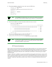
4. Enter the add ATMRoute command to create a static route to the IISP device:
SmartCell ZX # add atmroute
PortNumber(A1) : b2
AtmAddress() : 52:00:00:00:00:00:00:00:00:00:14:51:80
PrefixLength(104) :
Index(0) :
Type(Internal) :exterior
Scope(0) :
MetricsTag(0) :
SmartCell ZX #
Note The add ATMRoute command allows you to specify a set of metrics to be used with
the route. For more on metrics and metric tags, see Section 4.2.3 “Route Metrics.”
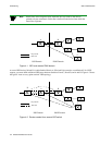
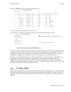
5. Enter the show ATMRoute command to determine whether the route was created:
SmartCell ZX # show atmroute
AddressNumber(ALL) :
No. Port Route Address Type Protocol
================================================================================
1 B4 39:00:00:00:00:00:00:00:00:00:14:41:80:00:20:d4:14:41:80 I MGMT
2 B4 39:00:00:00:00:00:00:00:00:00:14:41:80:00:20:d4:14:41:81 I MGMT
3 -- 39:00:00:00:00:00:00:00:00:00:14:59:00 I PNNI
4 -- 39:00:00:00:00:00:00:00:00:00:28:e9:80 I PNNI
5 -- 39:00:00:00:00:00:00:00:00:00:28:f5:00 I PNNI
6 B4 47:00:79:00:00:00:00:00:00:00:00:00:00:00:a0:3e:00:00:01 I MGMT
7 B2 52:00:00:00:00:00:00:00:00:00:14:51:80 I MGMT
SmartCell ZX #
The route to the IISP device appears on the last line (Route No. 7).
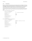
6. Create a route on the IISP device that refers to the net prefix
(
39:00:00:00:00:00:00:00:00:00:14:41:80) of port b2 on the SmartCell 6A000.
Note For IISP routes to work with certain devices, ILMI may also need to be disabled
on the SmartCell 6A000. Use the
set PortConfig command to disable ILMI on
the SmartCell 6A000 on a per-port basis.
IISP Routing Considerations
When creating routes between the SmartCell 6A000 (running PNNI) and IISP devices, the criteria that characterize
IISP connectivity still apply. To reach a SmartCell 6A000 within the PNNI domain, the IISP device must have a
configured route that points directly to a port on the target SmartCell 6A000. Conversely, there must be a SmartCell
6A000 that has a direct physical link (and a route over that link) to the IISP device. The following two examples
illustrate this point.
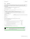
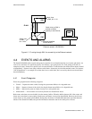
In Figure 4-1 Switch A is an IISP device connected to the PNNI domain through Switch B. Switch A contains an LEC,
which is a member of an ELAN whose LECS is on Switch C (within the PNNI domain). If the LEC on Switch A is to
make contact with the LECS on Switch C, Switch A must contain an IISP route (denoted by the dotted line) directly
to switch C. Furthermore, Switch B must contain a route to switch A over the physical link that connects the two
switches.