


4-4 SmartCell 6A000 User Guide
ATM Routing Switch Administration
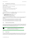
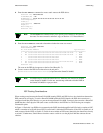
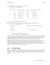
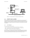
Note Dotted lines in the diagrams below represent one-way routes to the devices
pointed to by the arrowheads. Each route is defined on the device from which the
dotted line originates.
Figure 4-1 IISP route across PNNI domain
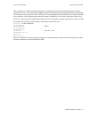
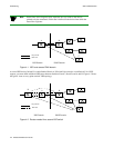
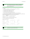
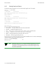
A second IISP device (Switch D) is added behind Switch A. If Switch D also needs to reach Switch C for LECS
support, you must define additional IISP routes between Switches D and C, B and D, and A and D. Figure 4-2 shows
the typical “route to every point reached” IISP topology.
Figure 4-2 Routes needed for a second IISP switch
A
B
C
LEC
LECS
Physical link
IISP route
IISP Domain PNNI Domain
B
C
LECS
A
LEC
D
Physical link
IISP route
LEC
IISP Domain PNNI Domain