


4-14 SmartCell 6A000 User Guide
PVC Connections Switch Administration
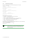
6. Configure the workstations for the same subnet and VPI/VCI pair = 0/101.
The broadcasting workstation on port A1 can send traffic to the receiving workstations on ports B2, B3, and C1.
4.5.3 Connecting to Local Switch Client Through a PVC
All PVC connections to the SmartCell 6A000 local clients use B4 (the CPU port) as the HighPort.
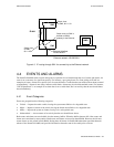
Follow these instructions to connect an end node to a SmartCell 6A000 local client through a point-to-point PVC.
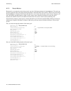
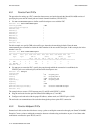
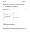
1. Use add pvc to create the PVC.
SmartCell ZX # add pvc
ConnType(PTP) :
<we use a point-to-point PVC
LowPortID() : a1
<for this example, we connect through port a1
LowVPI() : 0
LowVCI() : 100
HighPortID() : b4
<HighPort must be b4
HighVPI() : 0
HighVCI() : 100
FwdTrafficDescriptorIndex() : 2
BkwTrafficDescriptorIndex() : 2
SmartCell ZX #
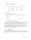
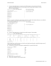
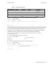
2. Use add ipatmclient to create the IP over ATM local client.
SmartCell ZX # add ipatmclient
ClientNumber(0) : 2
<we use client # 2 in this example
ServerType(NONE) : local
<ARP server on the switch
ServerAddress() :
IPAddress() : 10.1.1.0
NetMask(255.0.0.0) :
MTU(9180) :
SmartCell ZX #
3. Use add ipatmpvc to associate the end node’s IP address with the PVC.
SmartCell ZX # add ipatmpvc
ClientNumber(0) : 2
<specify local client number
DestinationIP() : 10.1.1.22
<end node’s IP address
DestinationVPI(0) :
DestinationVCI(33) : 100
<VCI was specified as 100
SmartCell ZX #
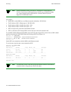
4. Connect the end node to port A1 of the SmartCell 6A000.
5. Configure the end node with IP address 10.1.1.22, subnet mask 255.0.0.0, and VPI/VCI pair = 0/100.
4.5.4 Non-zero VPIs
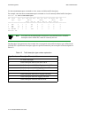
The SmartCell 6A000 uses 12 bits to define VPI/VCI pairs. The vccmask determines how many of the 12 bits are used
for the VPI and how many are used for the VCI. The
vccmask uses a 2-bit register to hold four different VPI/VCI 12-bit
combinations. Table 4-1 shows the registers and the values that come preconfigured on the SmartCell 6A000.