Ethernet Interface Configuration
6H128-08 and 6H129-08 User’s Guide 5-67
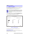
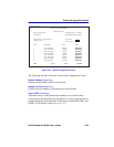
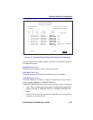
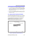
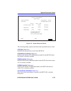
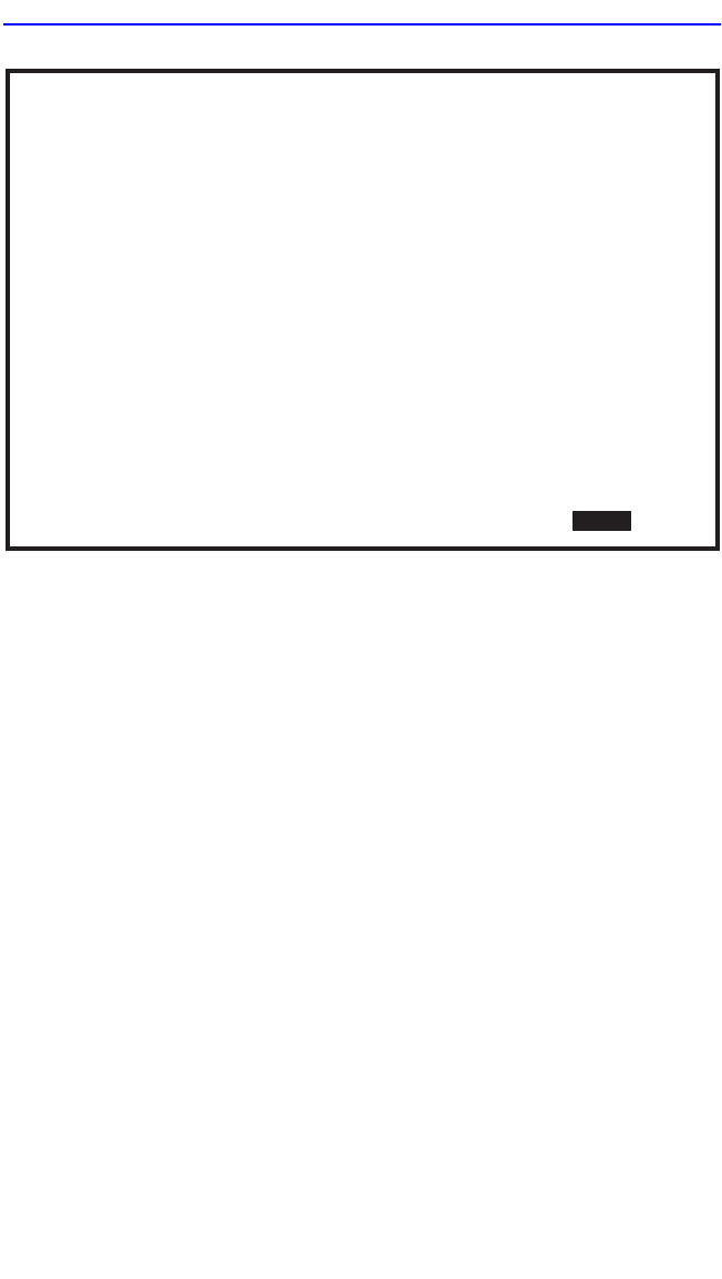
Figure 5-25 Ethernet Interface Configuration Screen for the 6H12X-08
The following section briefly explains each field of the Ethernet Interface
Configuration screen:
Port Num (Read-only)
Displays the port number of the front panel interface.
Port Type (Read-Only)
Displays the name of the interface installed in ports 1 through 8.
Link Status (Read-Only)
Indicates whether or not there is a physical connection from a particular
port to another 10BASE-T, 100BASE-TX/FX, or
100BASE-TXFD/FXFD device. One of the following values is displayed:
• Link – There is a link signal present and a valid physical connection to
another 10BASE-T, 100BASE-TX/FX, or 100BASE-TXFD/FXFD
device.
• No Link – There is no link signal present and there is no valid physical
connection to another device.
Ethernet Interface Configuration
2159-23
Firmware Revision: XX.XX.XX
BOOTPROM Revision: XX.XX.XX
Module Type: 6H128-08
Slot Number:
X
6H128-08 LOCAL MANAGEMENT
Event Message Line
RETURN
SAVE
Port
Num
1
2
3
4
5
6
7
8
FE-100FX
FE-100FX
FE-100FX
FE-100FX
FE-100FX
FE-100FX
FE-100TX
FE-100FX
Port
Type
Link
Status
No Link
No Link
No Link
No Link
Link
No Link
No Link
Link
Current
Oper. Mode
100Base-FXFD
100Base-FXFD
100Base-FXFD
100Base-FXFD
100Base-FXFD
100Base-TX
100Base-FXFD
Desired
Oper. Mode
[100Base-FX]
[100Base-FXFD]
[100Base-FXFD]
[100Base-FXFD]
[100Base-FXFD]
[100Base-FXFD]
[100Base-TX]
[100Base-FXFD]
Advertised Ability
100Base-FX N/A
N/A
N/A
N/A
N/A
N/A
100Base-TXFD
N/A
EXIT
[Disabled]


