Appendix C: Optional Installations and Mode Switch Bank Settings
C-2 6H128-08 and 6H129-08 User’s Guide
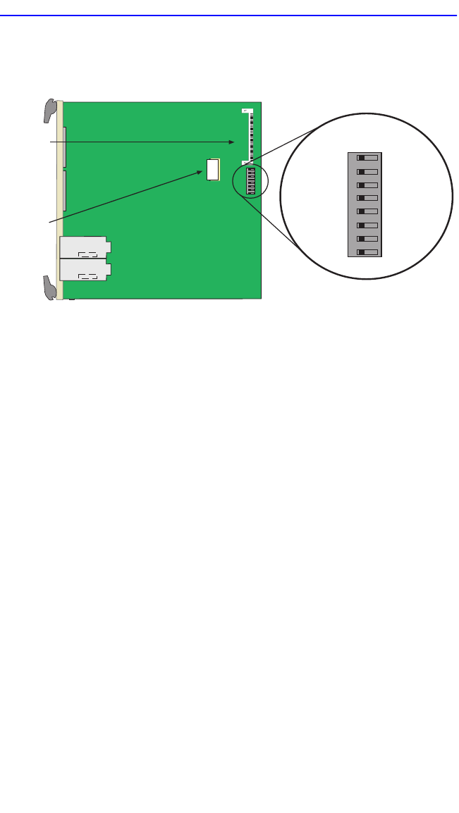
Figure C-1 shows the location of the mode switches and the switch
settings for normal operation.
Figure C-1 6H12X-08 Mode Switch Location/Component Layout
Switch definitions and positions are as follows:
• Switches 1 through 4 – For Cabletron Systems use only.
• Switch 5 – COM Port Autobaud. The default (OFF) position enables
Autobaud sensing on the COM port for Local Management sessions.
Changing the switch to the ON position disables Autobaud sensing and
sets the COM port to 9600 baud for Local Management sessions.
• Switch 6 – Forced BootP. Changing the position of this switch (i.e.,
moving the switch from one position to the other) clears download
information from NVRAM and forces the 6H12X-08 to download a
new image file from a BootP server after power to the chassis is
restored.
After changing the position of switch 6 and restarting the module, the
6H12X-08 requests a new image download until it either receives a
new image or the RESET button on the front panel is pressed. When
the RESET button is pressed, the 6H12X-08 continues trying to
contact a BootP server, but will time out in approximately one minute.
If the module times out, the image is downloaded from its FLASH
memory.
Flash
DRAM
MODE SWITCH
1
2
3
4
5
6
7
8
OFF ON
2159_34


