


Chapter 3: Installation
3-10 6H128-08 and 6H129-08 User’s Guide
e. Confirm that the crossover switch is in the correct position.
If a link has not been established, refer to Appendix B and Chapter 4
before contacting the Cabletron Systems Global Call Center. Refer to
Section 1.7 for details.
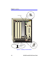
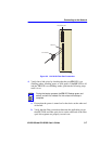
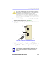
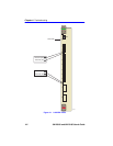
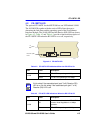
3.4.3 Connecting a Fiber Optic Segment to the
FE-100FX and FE-100F3
The FE-100FX and FE-100F3 have an SC style network port (see
Figure 3-5). Cabletron Systems offers optional fiber optic cables that use
SC style connectors. These connectors are keyed to ensure proper cross
over of the transmit and receive fibers. The FE-100FX is designed for use
with multimode fiber, and the FE-100F3 is designed to use single mode
fiber. Use of the incorrect fiber type may cause network problems. Please
refer to the Cabletron Systems Cabling Guide for further information.
Fiber Optic Network Connection
To connect a fiber optic segment, proceed as follows:
1. Remove the protective rubber covers from the fiber optic ports on the
applicable port on the module and from the ends of the SC connectors.
NOTE
See Appendix B for more information describing how an
FE-100TX module links to another device.
!
CAUTION
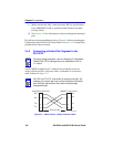
An odd number of crossovers (preferably one) must be
maintained between devices so that the transmit port of one
device is connected to the receive port of the other device and
vice versa.
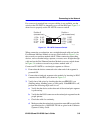
If the fiber optic cable being used has SC style connectors that
do not resemble MIC style connectors, or has SC connectors
on one end and a different type on the other, such as ST
connectors, ensure that the proper crossing over occurs.