


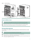
17
Recommended Tools and Supplies
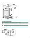
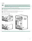
Attach the Grounding Cable
Warning
When installing the unit, always make the ground connection first and disconnect it last.
Statement 42
Warning
Use copper conductors only.
Statement 1025
Warning
Before performing any of the following procedures, ensure that power is removed from the DC circuit. To ensure
that all power is OFF, locate the circuit breaker on the panel board that services the DC circuit, switch the circuit
breaker to the OFF position, and tape the switch handle of the circuit breaker in the OFF position.
Statement 7
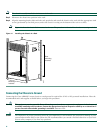
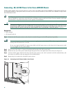
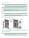
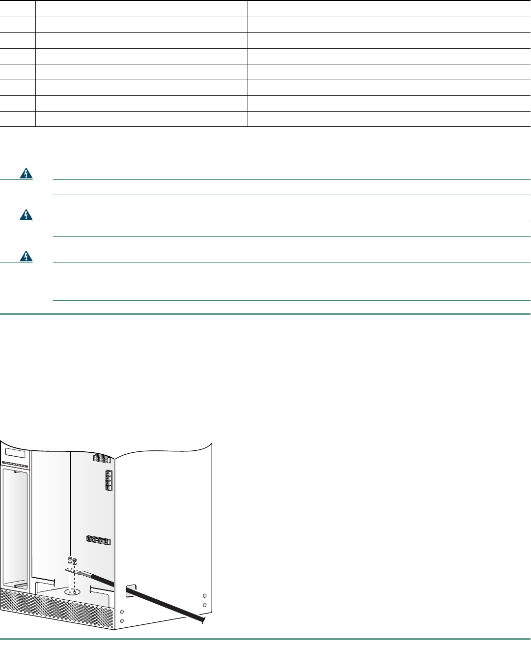
Step 1 Verify that no power source is connected to the Cisco uBR10012 chassis (the PEMs are not installed yet).
Step 2 Strip about 3/4 in. (2 cm) of the covering from the end of the grounding wire.
Step 3 Insert the stripped end of the grounding wire into the open end of the grounding lug, and crimp the grounding lug
securely to the wire. See Figure 12.
Step 4 Using the two M5 screws provided in the accessory kit, fasten the grounding lug firmly to the bottom of the chassis.
Step 5 Attach the other end of the ground cable to a suitable grounding location in accordance with local practice at your site.
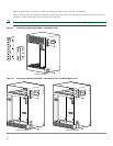
Figure 12 Ground Location
Qty Description Comments
1 Number 2 Phillips screwdriver —
1 Wire stripping tool —
1 Crimping tool Must fit diameter of grounding lugs.
1 2-hole grounding lug Included in accessory kit shipped with the Cisco uBR10012 router.
1 Grounding wire 6 AWG (16 mm
2
), customer provided.
2 M5 PEM screws with captive, locking washers Included in accessory kit shipped with the Cisco uBR10012 router.
1 Antistatic mat and ESD-wrist strap —
98747