


26
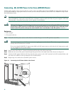
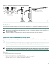
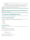
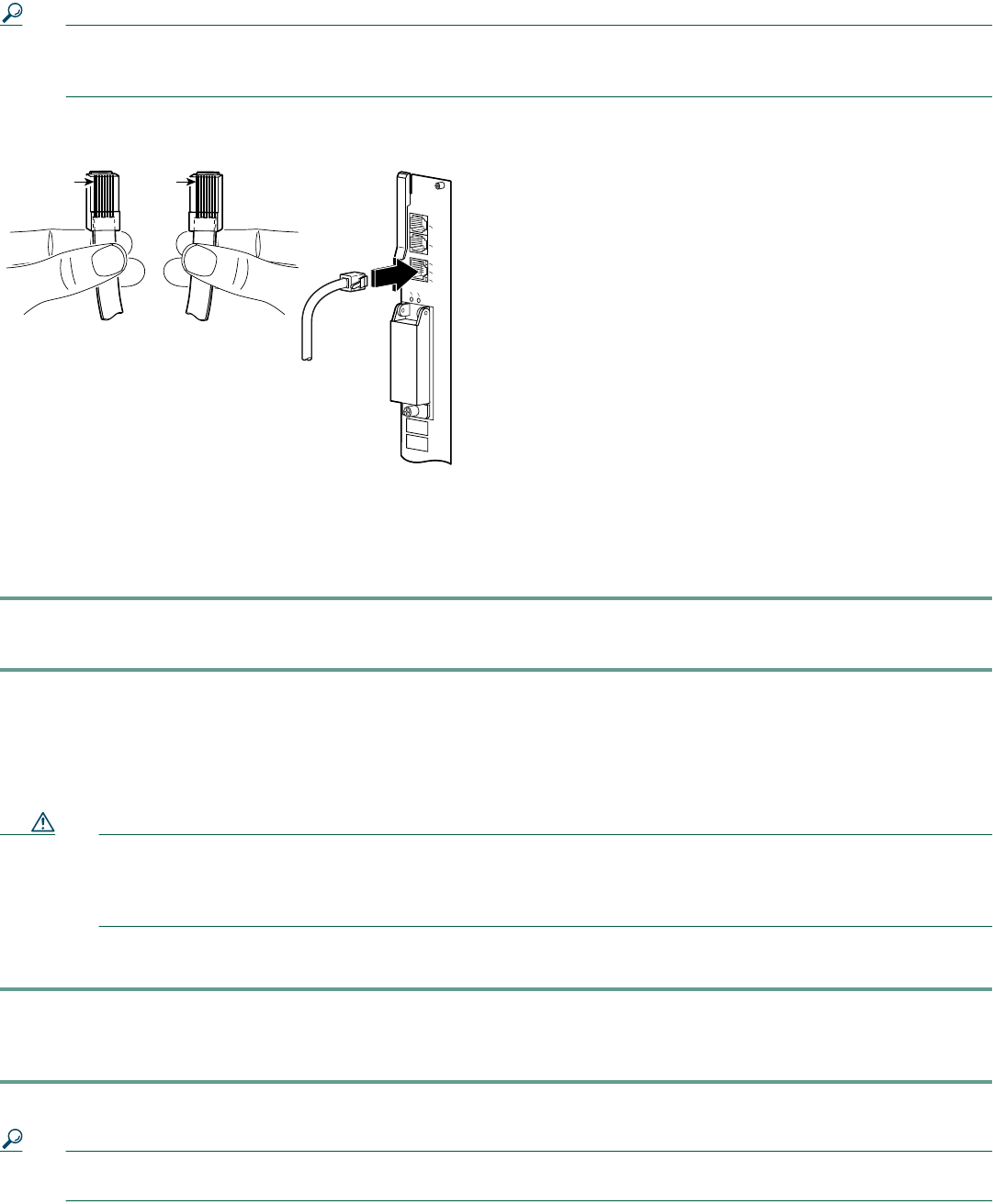
Tip The color of the wire connected to pin 1 (left-most) on the connector at one end of the cable, should be the same color
as the wire connected to the left-most pin on the connector at the other end of the cable. The same rule applies to pins
2 through pin 8 on each connector.
Figure 21 Straight-Through Cable
10BASE-T Ethernet Network
To connect the PRE to a 10BASE-T Ethernet LAN, follow this procedure:
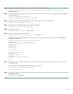
Step 1 Connect one end of the Ethernet cable to the RJ-45 port on the primary PRE labeled Ethernet.
Step 2 Connect the other end of the cable to any unoccupied port on the Ethernet hub.
100BASE-T Ethernet Network
The RJ-45 port on the PRE is configurable for 100-Mbps full-duplex or half-duplex operation (half-duplex is the default) and
supports IEEE 802.3, Ethernet, and IEEE 802.3u interfaces compliant with 100BASE-T specifications.
Caution If the Cisco uBR10012 router is used in an environment in which lightning-induced transients are likely to couple
to the signal lines, use of shielded interconnection cables for the 100BASE-T ports is highly recommended. In
addition, use of shielded interconnection cables for the 100BASE-T ports is required to meet Telcordia GR1089
CORE Section 4.5.9 and ETSI Section 5.2.2.2 (intra-building lightning surge).
To connect the PRE to a 100BASE-T Ethernet LAN, follow these steps:
Step 1 Connect one end of the Ethernet cable to the RJ-45 port on the primary PRE, labeled Ethernet.
Step 2 Run the cable up and through the cable management bracket and connect the other end of the Ethernet cable to any
unoccupied port on the Ethernet hub.
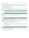
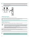
Tip When power is applied to the chassis, check the LNK (Link) LED on the PRE faceplate port next to the Ethernet port.
This LED comes on (green) if the PRE is correctly connected to the Ethernet LAN.
98752
CONSOLE
ETHERNET
LINK
AUX
S
L
O
T
0
S
LO
T 1
CISCO
10000
LINK
Pin 1 Pin 1
Ethernet port
How to identify a
straightthrough cable