


7
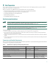
Fiber-Optic Connections
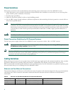
The specifications for single-mode, fiber-optic transmissions are outlined in Table 3.
Note Do not exceed the specified distance limits.
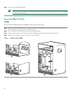
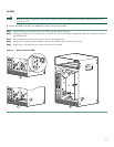
4 Chassis Installation
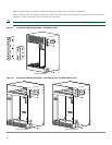
Tip For easier installation, rest the chassis on an installation shelf while installing the chassis in a rack.
Rack-Mounting Guidelines
• Allow sufficient clearance around the rack for maintenance.You need 36 in. (91.44 cm) of clearance to remove and replace
system components.
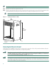
• If the Cisco uBR10012 chassis is the only unit in a rack, mount the chassis at the bottom of the rack. Use the rack-mount
kit that comes with the Cisco uBR10012 chassis.
• Always place the heavier equipment in the lower half of the rack.
• If the rack is provided with stabilizing devices, install the stabilizers before mounting the chassis.
• Make sure that Telco racks are bolted to the floor.
• When mounting the chassis in 4-post or Telco racks, use all the screws and brackets that are provided.
• For 23-inch racks, order optional mounting brackets from third-party vendors.
Installation Tools and Equipment
The tools and equipment listed below are recommended as the minimum necessary to install the Cisco uBR10012 router. Other
equipment may include test equipment to check electronic and optical signal levels, power levels, and communications links.
• Rack-mounting kit (includes brackets and screws)
• Screwdrivers
–
Number 2 Phillips screwdriver
–
3/16-inch flat-blade screwdriver
–
1/4-inch flat-blade screwdriver
• Antistatic mat or antistatic foam and electrostatic discharge (ESD) grounding strap or the disposable ESD strap
• Wire stripper and crimping tool for preparing the ground connection (the accessory kit comes with ground lugs and M5
screws with captive, locking washers)
• Wire—6 AWG (16 mm), customer provided
• Tape measure and level (optional)
• Cable mounting brackets and ties (optional), used with RF switch
Table 3 Fiber-Optic Transmission Characteristics
Characteristic Permissible Value Characteristic Permissible Value
Transmitter output power –15 to –8 dBm Wavelength 1261 to 1360 nm
Receiver sensitivity –28 to –8 dBm Maximum span 9 miles (14.5 km)