


29
• The console terminal or modem is cabled and turned on.
• A PCMCIA flash memory card is installed in the PRE module.
You are now ready to power on the system for the first time using the following procedure.
DC PEM
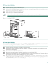
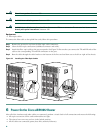
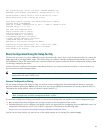
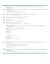
Step 1 Verify that each DC PEM is turned OFF (0). See Figure 23.
Step 2 Remove the tape from the circuit breaker switch handle.
Step 3 Turn on power at the power supply that is suppling the DC power for the chassis.
Note If you are using the 2400-W AC-input power shelf, this step requires plugging the three AC power cords into the back
of the unit and into the outlets providing the AC power source. The AC OK and DC OK LEDs on the AC-input power
shelf should both come on, indicating that both AC input and DC output power is present.
Step 4 After turning on the DC power source, verify that the FAULT LED on each PEM comes on (yellow), indicating that the
PEM is receiving power from the DC power source but is not yet supplying power to the chassis (because its power
switch is off). If the Fault LED does not come on,
a. Turn off the DC power source.
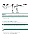
b. Verify that the wiring from the DC power source to the two terminal blocks underneath each DC PEM is correct, as
described in the “Connecting –48/–60 VDC Power to the Cisco uBR10012 Router” section on page 18.
Tip If the miswire LED comes on for either PEM, it indicates that the two wires from the DC source (–48/–60 VDC and
RTN) were reversed when connected. Turn off the DC power source and reverse the two wires so that the –48/–60 VDC
lead is connected to the bottom terminal and the RTN lead is connected to the top terminal.
Step 5 Turn the power switch on each DC PEM to the ON (|) position.
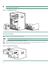
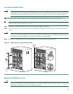
Figure 23 Cisco uBR10012 Router DC and AC PEM Power Switches
Step 6 Verify that all LEDs are coming on properly:
a. The Power LED on each PEM is on (green), indicating that power is being received and is being delivered to the chassis.
If the other LEDs on the PEM (Miswire or Fault) come on (yellow), see the “Troubleshooting” section on page 35.
b. Listen to the fans as power is applied. When you first apply power to the chassis, the fans in the fan assembly module
initially operate at high speed. If all four fans are operating correctly, and if the temperature of the chassis is in the
nominal operating range, the fans slow down to their normal operating speed.
c. The OK LED on the fan assembly module is on (green), indicating that all fans in the blower are operating properly. You
should be able to feel air being taken in at the bottom front of the chassis and being blown out at the top rear of the
chassis.
A
L
A
R
M
S
F
A
I
L
PERFORMANCE ROUTING ENGINE
S
T
A
T
U
S
A
C
O
C
R
I
T
I
C
A
L
M
I
N
O
R
M
A
J
O
R
A
L
A
R
M
S
F
A
I
L
PERFORMANCE ROUTING ENGINE
S
T
A
T
U
S
A
C
O
C
R
I
T
I
C
A
L
M
I
N
O
R
M
A
J
O
R
ON
ON
ON
ON
ON
ON
ON
ON
ON
A
L
A
R
M
S
F
A
I
L
PERFORMANCE ROUTING ENGINE
S
T
A
T
U
S
A
C
O
C
R
I
T
I
C
A
L
M
I
N
O
R
M
A
J
O
R
A
L
A
R
M
S
F
A
I
L
PERFORMANCE ROUTING ENGINE
S
T
A
T
U
S
A
C
O
C
R
I
T
I
C
A
L
M
I
N
O
R
M
A
J
O
R
ACINPUT
200-240V
13A 50/60Hz
AC
SWITCH
ACINPUT
200-240V
13A 50/60Hz
ACINPUT
200-240V
13A 50/60Hz
AC
SWITCH
98814
DC power switch in ON position AC power switch in ON position
AC
SWITCH