


25
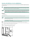
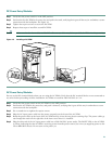
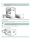
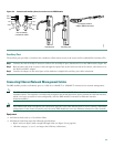
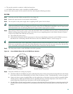
Figure 20 Console and Auxiliary Port Connection on the PRE Module
Auxiliary Port
The auxiliary port provides a connection for a modem to allow remote access to the router and its command-line interface (CLI).
Step 1 Connect one end of the RJ-45 crossover cable to the serial RJ-45 port (labelled AUX) on the PRE module (Figure 20).
Step 2 Run the other end of the crossover cable through the square hole at the left front side of the chassis, and connect it to
the RJ-45-to-DB-25 adapter.
Step 3 Connect the adapter to the serial port on the modem to complete the auxiliary port cable connection.
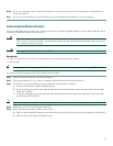
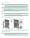
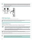
Connecting Ethernet Network Management Cables
The PRE module provides an Ethernet port to a LAN for a 10BASE-T or 100BASE-T connection for network management.
Note The PRE module also contains an internal Ethernet interface (ethernet0/0/0) that it uses for inter-module
communications. This interface is invisible and transparent for normal operation. Do not confuse this internal interface,
which is not user-accessible or user-configurable, with the PRE module’s external Fast Ethernet interface
(fastethernet0/0/0).
Note Each PRE module needs an Ethernet port connection (typically to the same Ethernet hub) if you are running a redundant
configuration in the chassis. However, only the active PRE module has an active Ethernet connection to the network.
Equipment
• An Ethernet hub (such as a Cisco Micro Hub)
• An Ethernet cable that meets the following specifications:
–
RJ-45 (male) to RJ-45 (male) straight-through cable (see Figure 21 on page 26)
–
100-ohm category 3, 4, or 5, no longer than 328 feet (100 meters)
98751
CONSOLE
ETHERNET
LINK
AUX
SL
O
T
0
S
LO
T
1
CISCO
10000
LINK
CONSOLE
ETHERNET
LINK
AUX
SL
O
T
0
S
LO
T 1
CISC
O
10000
LINK
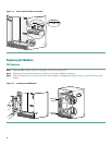
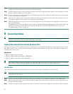
Pin 6
Pin 3
Pin 1
Pin 2
Console port Auxiliary port
Crossover cable to
DB9 or DB25 connector
How to identify
a crossover cable