


19
Step 6 If you are connecting visual or audio alarm indicators to your system, go to the “Connecting the Alarm Indicators”
section on page 19.
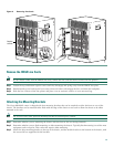
Step 7 If you are not connecting any alarm indicators, go to the “Replacing the Modules” section on page 20.
Connecting the Alarm Indicators
The Cisco uBR10012 router provides relay contacts for optional (customer-supplied) audible or visual alarm indicators. Relay
contacts are provided for three levels of severity.
Caution The alarm contacts on the Cisco uBR10012 router are only relays and do not provide any power from the unit.
These relays are rated for 60 VDC, 1 A maximum—ensure that the connected alarm equipment does not exceed
these voltage and current ratings.
Warning
Use copper conductors only.
Statement 1025
Equipment
• Two wires for each set of relays, or six separate wires to connect all three relay contacts
• Wire stripper
Tip Use the gauge of wire required by the audible or visual alarm indicator equipment you are using (14 AWG, max.)
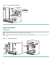
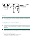
To connect an alarm indicator to the chassis, follow this procedure:
Step 1 Obtain sufficient wire for the desired connections.
Step 2 Strip approximately 0.31 in. (8 mm) of insulation off the ends of the alarm indicator wire.
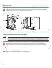
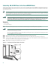
Step 3 Connect one set of alarm indicator wires to the alarm terminal block as follows:
a. Connect one lead to the common (COM) terminal.
b. If you are wiring the router in with other equipment for the alarm indicators, connect the other lead to the normally
closed (NC) terminal.
c. If you are wiring the router in parallel with other equipment for the alarm indicators, connect the other lead to the
normally open (NO) terminal.
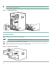
Note Figure 14 on page 20 shows the wiring configuration for NO alarm relays. For NC alarm relays, use the NC contacts.
Step 4 Repeat Step 3 for the remaining alarm indicators
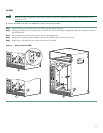
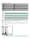
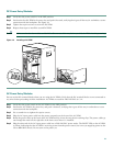
Step 5 Secure the alarm and power cabling to the chassis:
a. Feed a tie wrap through the square slot on the left front side of the chassis (next to the alarm indicator terminal block).
b. Bind the wires to the chassis using the tie wrap.