


24
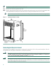
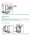
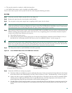
Step 1 Grasp the faceplate of the line card with one hand and place your other hand under the card carrier (to support the
weight of the card). Position the card in front of the slot splitter.
Step 2 Carefully align the upper and lower edges of the line card with the upper and lower guides in the slot splitter, and slide
the line card about half-way into the splitter.
Step 3 Be sure the ejectors are in the open position and continue to push the line card into the splitter until you can feel it begin
to seat in the backplane connectors.
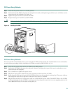
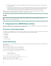
Step 4 Verify that the captive screws are properly aligned with the captive screw holes in the splitter. If the captive screws are
not properly aligned, the card will not seat properly in the backplane.
Step 5 Simultaneously pivot both ejector levers toward each other (until they are parallel to the faceplate) to firmly seat the
card in the backplane.
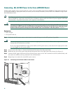
The HHGE line card cycles through its power-on self-test. The FAIL LED lights during portions of the POST (Power-On
Self Test), but remains off after POST on a properly working line card. If the FAIL LED remains on, go to the
“Troubleshooting” section on page 35.
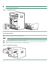
5 Connecting Cables
Tip To reduce the chance of interference, avoid crossing the power cables with any of the interface cables. Verify all cabling
limitations (particularly distance) before powering on the system.
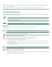
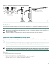
Connect the Console Port and the Auxiliary Port
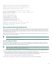
See Figure 20 on page 25. The PRE module has two asynchronous serial (EIA/TIA-232) RJ-45 ports for connection to a console
(an ASCII terminal or a PC running terminal emulation software) and modem for remote access. The cables and adapter are
included in the accessory kit.
Equipment
• RJ–45 to RJ–45 crossover cable
• RJ–45 to DB–9 female DTE adapter (TERMINAL)
• RJ–45 to DB–25 male DCE adapter (MODEM)
Tip The crossover cable reverses the pins from one end of the cable to the other. The color of the wire at pin 1 is the same
color as the wire at pin 8 on the opposite end of the cable (pin 2 to pin 7, pin 3 to pin 6, and so on.).
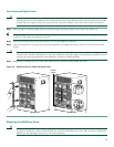
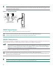
Console Port
The console port provides local administrative access to the router and its command-line interface (CLI).
Note Each PRE module must have a console port connection (typically to a terminal server) when running a redundant
configuration in the chassis.
Step 1 Connect one end of the RJ-45 crossover cable to the serial RJ-45 port (labeled CONSOLE) on the PRE module.
Step 2 Run the other end of the crossover cable through the square hole at the left front side of the chassis, and connect it to
the RJ-45-to-DB-9 adapter.
Step 3 Connect the adapter to the appropriate serial port on the PC or terminal to complete the console port cable connection.