


1-4
Cisco Aironet 1400 Series Wireless Bridge Hardware Installation Guide. OL-4072-03
OL-4072-04
Chapter 1 Overview
Key Features
Integrated Antenna
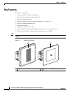
The bridge is available with an integrated 22.5-dBi or 20-dBi patch array antenna. The antenna is
covered with a radome to protect it from environmental elements. When configured with the integrated
antenna, the antenna polarization is controlled by the mounting orientation of the bridge. The bridge
must be physically rotated 90 degrees to obtain either horizontal or vertical polarization. An arrow
indicating polarization is designed into the bridge housing to indicate the polarization direction.
Note The 20-dBi integrated is available only on the low power bridge version for Korea.
Note Some international regulatory regions may restrict the integrated antenna bridge configuration.
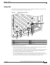
Ethernet Ports
The bridge’s power injector dual-coax ports accept a pair of 75-ohm F-type connectors, linking the
bridge to your 100BASE-T Ethernet LAN through the power injector. The dual-coax cables are used to
send and receive Ethernet data and to supply inline 48-VDC power from the power injector. For the
location of the ports, refer to Figure 1-2.
Tip You can connect the dual-coax cable connectors to either of the bridge’s power injector dual-coax ports.
The bridge senses the Ethernet signals and automatically switches internal circuitry to match the cable
connections.
Metal Enclosure
The bridge uses a metal enclosure that supports outdoor operating environments and supports an
industrial temperature operating range (refer to “Bridge Specifications” section on page 1-8).