


2-6
Cisco Aironet 1400 Series Wireless Bridge Hardware Installation Guide. OL-4072-03
OL-4072-04
Chapter 2 Installation Overview
Before Beginning the Installation
Package Contents
Each bridge package contains the following items:
• Bridge unit
• Power injector unit (with mounting screws and wall anchors)
• Power module and AC power cord (with mounting screws and wall anchors)
• Two dual-coax cables [20 ft (6.1 m) and 50 ft (15.2 m)]
• Mounting kit and hardware
–
Multi-function mount (consisting of two bridge brackets and one tower or mast bracket)
–
Two tower clamps (U-bolts) with four nuts and washers
–
Four bolts, lock washers, and washers for securing the bridge brackets to the tower or mast
bracket
–
Four bolts and lock washers for securing the bridge brackets to the bridge
• Grounding block and mounting screws
• Ground lug for the bridge with screws
• Weatherproofing kit (consisting of Coax Seal and electrical joint compound)
• Quick Start Guide: Cisco Aironet 1400 Series Wireless Bridge
• Cisco Aironet 1400 Series Wireless Bridge Mounting Instructions
• Cisco product registration and Cisco documentation feedback cards
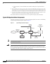
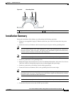
Before Beginning the Installation
Before you begin the installation process, please carefully review the following list of figures to become
familiar with the system components, connectors, indicators, cables, system interconnection, and
grounding:
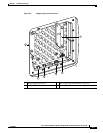
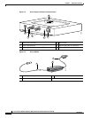
• Bridge Installation diagram (Figure 2-1)
• Bridge layout (Figure 2-2)
• Power injector layout (Figure 2-3)
• Power module (Figure 2-4)
• Grounding block (Figure 2-5)