


1-5
Cisco Aironet 1400 Series Wireless Bridge Hardware Installation Guide. OL-4072-03
OL-4072-04
Chapter 1 Overview
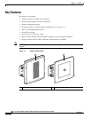
Key Features
Bridge LEDs
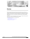
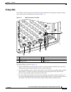
Four LEDs are located on back of the housing to report installation and alignment conditions, bridge
status, radio activity, and Ethernet activity (see Figure 1-2).
Figure 1-2 Bridge Connectors and LEDs
The bridge LEDs are shown in Figure 1-2.
• The install LED indicates that installation mode is activated. During installation mode, the other
LEDs provide signal strength readings used for antenna alignment.
• The radio LED blinks green to indicate radio traffic activity. The light is normally off, but it blinks
green whenever a packet is received or transmitted over the bridge radio link. This LED also
provides signal strength readings during installation mode.
• The status LED signals bridge association status. Blinking green indicates that the bridge is not
associated with another bridge. Steady green indicates that the bridge is associated with at least one
other bridge. This LED also provides signal strength readings during installation mode.
1 Power injector dual-coax ports 4 Status LED
2 RSSI voltage port 5 Radio LED
3 Ethernet LED 6 Install LED
6
1
1
2
3
5
4
88777