


6-5
Cisco Aironet 1400 Series Wireless Bridge Hardware Installation Guide. OL-4072-03
OL-4072-04
Chapter 6 Troubleshooting
Power Injector LEDs
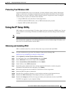
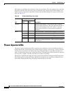
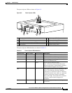
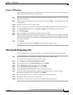
The power injector LEDs are shown in Figure 6-2.
Figure 6-2 Power Injector LEDs
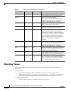
The power injector LED indications are shown in Table 6-3.
1 Power jack (+48 VDC) 5 Ethernet port (RJ–45 connector)
2 Power LED 6 Ethernet Activity LED
3 Power injector dual-coax ports (F-Type connectors) 7 Injector Status LED
4 Mode button 8 Uplink Activity LED
88820
1
2
4
5
8
7
6
3
Ipsamy opsum
Ipsamy opsum
Ipsamy opsum
Table 6-3 Power Injector LED Indications
Uplink Activity Injector Status Ethernet Activity Description
— — Off Wired LAN Ethernet link is not active.
— — Green Wired LAN Ethernet link is operational.
— — Blinking Green Transmitting and receiving packets over the
wired LAN Ethernet link.
— — Amber Power injector internal memory
error—disconnect and reconnect the power
injector power plug. If the problem continues,
contact technical support for assistance.
Off — — Link between power injector and bridge is not
active. This might be caused by improper
connections or a defective cable or connector.
Verify that the dual-coax cables are connected
correctly to the power injector, grounding
block, and bridge. If the cables are connected
correctly, contact technical support for
assistance.
Green — — Link between power injector and bridge is
operational.