


4-2
Cisco Aironet 1400 Series Wireless Bridge Hardware Installation Guide. OL-4072-03
OL-4072-04
Chapter 4 Stacking Bridges
Overview
Overview
You can double the throughput, or create a standby link, by stacking two bridges. A stacked installation
consists of two bridge systems installed at the same physical location. For detailed mounting instructions
refer to the Cisco Aironet 1400 Series Wireless Bridge Mounting Instructions that shipped with your
bridge.
Choosing a Second Mounting Location
You can mount the second bridge system in the same general location as the first as long as you separate
the antennas by at least 8 ft (2.44 m). For example, in a flat-roof installation you can separate the bridges
horizontally, roughly perpendicular to the line of signal propagation. In a tower installation, you can
separate the antennas vertically. During the activation process, you verify that the interference between
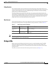
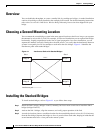
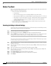
systems is acceptably low. Do not attempt to stack more than two bridges. Figure 4-1 identifies the
interference paths with stacked bridges.
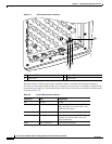
Figure 4-1 Interference Paths with Stacked Bridges
Installing the Stacked Bridges
To install stacked bridges, refer to Figure 4-1 as you follow these steps:
Step 1 Install the link 1 bridges (bridges A and C) normally, but leave room at each site to install the link 2
bridges (bridges B and C).
Step 2 Activate the link 1 bridges, align the antennas, and verify proper operation of the link.
Step 3 At each site location, choose a candidate location for the second bridge that is at least 8 ft (2.44 m) away
from the first bridge. Separate the bridges as far as is practical from each other, keeping in mind that the
second antenna must have a clear path to the remote system.
95008
Brdge B
Link 2
Link 1
Site 1 Site 2
Interference path
Brdge A
Brdge D
Brdge C