


2-9
Cisco Aironet 1400 Series Wireless Bridge Hardware Installation Guide. OL-4072-03
OL-4072-04
Chapter 2 Installation Overview
Installation Summary
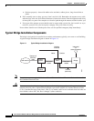
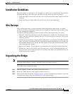
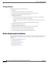
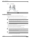
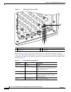
Figure 2-5 Grounding Block
Installation Summary
During the installation of the bridge, you will perform the following operations:
• Connect a user-supplied Category 5 Ethernet cable from your wired LAN network to the power
injector.
• Connect the dual-coax Ethernet cables between the power injector and the grounding block.
Tip You can connect the dual-coax cable connectors to either of the grounding block connectors or
the power injector’s dual-coax ports. The bridge senses the Ethernet signals and automatically
switches internal circuitry to match the cable connections.
Note You should securely tighten the cable connectors (15 to 20 inch-pounds) using a small wrench.
• Connect a ground wire to the grounding block.
• Mount the bridge to the external tower or mast. For additional information, refer to the Cisco Aironet
1400 Series Wireless Bridge Mounting Instructions that shipped with your bridge.
• Connect a ground wire to the bridge (use the bridge ground lug).
• Connect the dual-coax Ethernet cables to the grounding block and to the bridge.
Tip You can connect the dual-coax cable connectors to either of the grounding block connectors or
the bridge’s dual-coax ports. The bridge senses the Ethernet signals and automatically switches
internal circuitry to match the cable connections.
Note You should securely tighten the cable connectors (15 to 20 inch-pounds) using a small wrench.
• Connect the AC power cord to the 48-VDC power module.
1 F-type coaxial connectors 2 Ground wire lug
88830
1 1 2