


1-6
Cisco Aironet 1400 Series Wireless Bridge Hardware Installation Guide. OL-4072-03
OL-4072-04
Chapter 1 Overview
Network Configuration Examples
• The Ethernet LED signals Ethernet traffic. This LED blinks green when a packet is received or
transmitted over the Ethernet infrastructure. The LED is off when the Ethernet link not working or
the port is shutdown. This LED also provides signal strength readings during installation mode.
For additional information on the LEDs, refer to “Checking the Bridge LEDs” section on page 6-2.
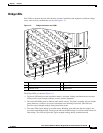
Receive Signal Strength Indicator Port
The bridge supports a receive signal strength indicator (RSSI) port for use in antenna alignment. The
RSSI port produces a DC voltage proportional to the strength of the received radio signal. The highest
voltage indicates the best antenna alignment position. The RSSI port is a female BNC connector located
on the bottom of the bridge housing (see Figure 1-2).
Note The RSSI port requires the use of a voltmeter and a cable with a male BNC connector.
Network Configuration Examples
This section describes the bridge’s role in three common wireless network configurations.
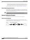
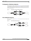
Point-to-Point Configuration
In a point-to-point configuration, two bridges connect two remote LAN networks using a wireless
communication link (see Figure 1-3). The bridge connected to the main LAN network is classified as a
root bridge and the other bridge is classified as a repeater bridge.
Figure 1-3 Point-to-Point Bridge Configuration
88833
Bridge Bridge