


3-6
Cisco Aironet 1400 Series Wireless Bridge Hardware Installation Guide. OL-4072-03
OL-4072-04
Chapter 3 Mounting and Alignment Overview
Aligning the Antenna Using the RSSI Voltage
When using LEDs to maximize the signal, adjust the antenna until as many LEDs as possible are turned
on and the rest are blinking as fast as possible.
Aligning the Antenna Using the RSSI Voltage
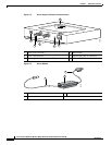
The RSSI port produces a DC voltage that is proportional to the received signal level. The RSSI voltage
is available whenever a signal is present, regardless of the bridge mode (installation or normal),
association status, or pre configuration role setting. In Install mode, the RSSI voltage provides an
instantaneous reading as you move the antenna. In Normal mode, the RSSI reading has a delay, so you
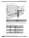
must stop moving the antenna and wait before taking your reading. The RSSI port is a female BNC
connector on the bridge housing (see Figure 3-1).
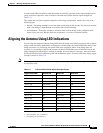
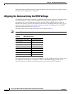
The RSSI voltage increases linearly with signal level as shown in Table 3-4.
Note A larger RSSI voltage reading indicates a stronger signal.
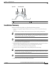
The voltage varies from 0 to 2.7 volts for signals between –90 and –20 dBm, respectively. The accuracy
over temperature and component variations is ± 4 dB. To obtain RSSI readings, you can use any
convenient voltmeter connected to the RSSI port using a cable with a male BNC connector.
Table 3-4 RSSI Voltage Levels
Nominal Signal Level (dBm) RSSI Reading (volts)
–20 or greater 2.70
–30 2.31
–40 1.93
–50 1.54
–60 1.16
–70 0.77
–80 0.39
–90 or less 0.00