


6-2
Cisco Aironet 1400 Series Wireless Bridge Hardware Installation Guide. OL-4072-03
OL-4072-04
Chapter 6 Troubleshooting
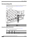
Checking the Bridge LEDs
Checking the Bridge LEDs
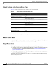
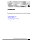
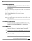
If your bridge is not associating with the remote bridge, check the four LEDs on the back panel. You can
use them to quickly assess the unit’s status. For information on using the LEDs during the installation
and alignment of the bridge antenna, refer to the “Bridge LEDs” section on page 3-3.
Figure 6-1 shows the bridge LEDs.
Figure 6-1 Bridge LEDs
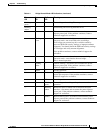
Bridge Normal Mode LED Indications
During bridge operation the LEDs provide status information as shown in Table 6-1.
1 Ethernet LED 3 Radio LED
2 Status LED 4 Install LED
88818
4
1
3
2
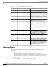
Table 6-1 Bridge Normal Mode LED Indications
Ethernet
LED
Status
LED
Radio
LED
Meaning
Off — — Ethernet link is down or disabled.
Green — — Ethernet link is operational.