


1-8
Catalyst 3750-E and Catalyst 3560-E Switch Hardware Installation Guide
OL-9774-03
Chapter 1 Product Overview
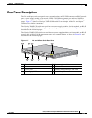
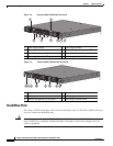
Front Panel Description
RPS LED
The RPS LED shows the RPS 2300 status. Table 1-4 lists the LED colors and their meanings. (Only 24-
and 48-port switches.)
Ta b l e 1-4 RPS LED
Color RPS Status
Off RPS is off or not properly connected.
Green RPS is connected and ready to provide back-up power.
Blinking green RPS is connected but is unavailable because it is providing power to another device
(redundancy has been allocated to a neighboring device).
Amber The RPS is in standby mode or in a fault condition. See the RPS 2300
documentation for more information about the standby mode and fault conditions.
Blinking amber The power supply in a switch has failed, and the RPS is providing power to that
switch (redundancy has been allocated to this device).
For more information about the RPS 2300, see the Cisco RPS 2300 Redundant Power System Hardware
Installation Guide on Cisco.com at this location:
http://www.cisco.com/en/US/products/ps7148/products_installation_guide_book09186a008075e608.ht
ml
Master LED
The Master LED shows the stack master status. Table 1-5 lists the LED colors and their meanings. (Only
Catalyst 3750-E switches.)
Ta b l e 1-5 Master LED
Color Description
Off Switch is not the stack master.
Green Switch is the stack master or a standalone switch.
Amber An error occurred when the switch was selecting the stack master
switch or another type of stack error occurred.
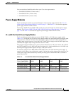
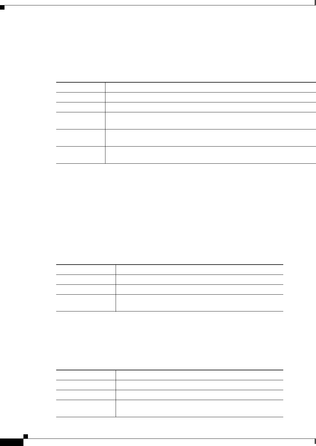
Power Supply LEDs
The Power Supply LEDs (PS1 and PS2) show the power supply status. Table 1-6 lists the LED colors
and their meanings. (Only Catalyst 3560E-12D and 3560E-12SD switches.)
Ta b l e 1-6 Power Supply LEDs
Color Description
Off No input power.
Green Input power present.
Amber Fault detected, or the on/off switch is set to off when the power
supply is plugged in.