


4-3
Catalyst 3750-E and Catalyst 3560-E Switch Hardware Installation Guide
OL-9774-03
Chapter 4 Troubleshooting
Diagnosing Problems
• Verify that both devices have power.
• Verify that you are using the correct cable type. See Appendix B, “Connector and Cable
Specifications” for more information.
• Check for loose connections. Sometimes a cable appears to be seated, but is not. Disconnect the
cable and then reconnect it.
PoE Connections
When a powered device is connected to PoE port, but no power is received, you should:
• Use the Mode button to show the PoE status for all ports. See Table 1-9 and Table 1-10 for a
description of the LEDs and their meanings.
• Check the port status by using the show interfaces privileged EXEC command to check the port
error-disabled, disabled, or shutdown status. Re-enable the port if necessary.
• Verify that the power supply installed in the switch meets the power requirements of your connected
devices. See the
“Power-Supply Modules” section on page 1-15 for more information.
• Check the cable type. Many legacy powered devices, including older Cisco IP phones and access
points that do not fully support IEEE
802.3af, might not support PoE when connected to the switch
by a crossover cable. Replace the crossover cable with a straight-through cable.
Caution PoE faults are caused when noncompliant cabling or powered devices are connected to a PoE
port. Only standard-compliant cabling can be used to connect Cisco pre-standard IP phones
and wireless access points or IEEE
802.3af-compliant devices to PoE ports. (You must
remove a cable or device that causes a PoE fault from the network.)
Transceiver Issues
Use only Cisco X2 transceiver modules and SFP modules on the switch. Each Cisco module has an
internal serial EEPROM that is encoded with security information. This encoding provides a way for
Cisco to identify and validate that the module meets the requirements for the switch. Check these items:
• Bad or wrong X2 transceiver, Cisco TwinGig Converter module, or SFP module. Exchange suspect
module with known good module. Verify that the module is supported on this platform. (The switch
release notes on Cisco.com list the X2 and SFP modules that the switch supports.)
• Use the show interfaces privileged EXEC command to check the port or module error-disabled,
disabled, or shutdown status. Re-enable the port if needed.
• Make sure that all fiber connections are properly cleaned and securely connected.
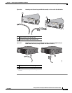
• For CX4 module connections, make sure that cable routing does not violate the minimum allowed
cable bend radius. See the module documentation for specific cabling requirements.
• For LX4 modules, a mode conditioning patch is recommended for MMF applications.
Port and Interface Settings
An obvious but sometimes overlooked cause of port connectivity failure is a disabled port. Verify that
the port or interface is not disabled or powered down for some reason. If a port or interface is manually
shut down on one side of the link or the other side, the link does not come up until you re-enable the