


B-3
Catalyst 3750-E and Catalyst 3560-E Switch Hardware Installation Guide
OL-9774-03
Appendix B Connector and Cable Specifications
Connector Specifications
SFP Modules
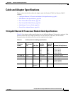
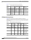
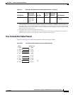
Figure B-4, Figure B-5, and Figure B-6 show the SFP module connectors.
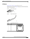
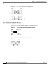
The Catalyst 3560-E switch supports the SFP module patch cable, a 0.5-meter, copper, passive cable
with SFP module connectors at each end (
Figure B-7). The patch cable can connect two Catalyst 3560-E
switches in a cascaded configuration.
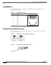
Figure B-4 Duplex LC Cable Connector
58476
Figure B-5 Simplex LC Cable Connector
57834
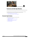
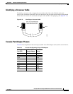
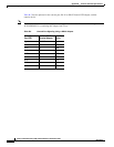
Figure B-6 Copper SFP Module RJ-45 Connector
60915
23145678Pin Label
1
2
3
4
5
6
7
8
TP0+
TP0-
TP1+
TP2+
TP2-
TP1-
TP3+
TP3-