


3-2
Catalyst 3750-E and Catalyst 3560-E Switch Hardware Installation Guide
OL-9774-03
Chapter 3 Power Supply and Fan Module Installation
Installation Overview
• Remove power from the power-supply module before removing or installing the module.
• The 24- and 48-port switch supports hot swapping of the power supply when the switch is connected
to an RPS
2300. You can remove and replace the power supply without interrupting normal switch
operation. When you insert a new power supply in the switch, there is a 5-second delay while the
switch software polls the device. The switch power supply then automatically provides power, and
the RPS
2300 is available to power other devices.
• The Catalyst 3560E-12D and 3560E-12SD switches support hot swapping of a power-supply
module when one of the two power supplies is active. You can remove and replace the power supply
without interrupting normal switch operation. When you insert a new power supply in the switch,
there is a 5-second delay while the switch software polls the device.
• The Catalyst 3560E-12D and 3560E-12SD switches can operate with only one active power-supply
module. However, two power supply modules must always be physically installed in the switch rear
panel when the switch is operating, even if one module is defective. This is required to maintain
adequate airflow in the chassis and prevent overheating. When the switch is running on only one
power-supply module, redundant failover and load sharing is not available.
Caution Do not operate the Catalyst 3560E-12D or 3560E-12SD switch with one power-supply module removed
from the rear panel. For proper chassis cooling, two power-supply modules must be installed in the
switch rear panel.
• For the Catalyst 3560E-12D and 3560E-12SD switch power-supply modules, we recommend that
you connect the power-supply modules to separate AC or DC circuits for optimal power reliability.
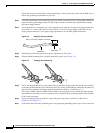
• The switch supports hot swapping of a fan module. When replacing a fan, you should complete the
replacement procedure within 2 minutes to avoid overheating the switch.
• The Catalyst 3560E-12D and 3560E-12SD switch continues to operate when there is one failed fan,
either a power-supply fan or a chassis cooling fan. If one fan fails, the switch returns an error
message. If a second fan fails, either a power supply fan or a chassis cooling fan, the switch returns
an error message, writes a failure log to flash memory, and shuts down.
• Make sure that all power supply and fan module captive screws are tightened before moving the
switch.
• When replacing the 24- and 48-port switch 1150-W or 750-W power supply, verify that you are
using the correct power cord (CAB-16AWG-AC, only in North America).
Warning
Do not reach into a vacant slot or chassis while you install or remove a module or a fan. Exposed
circuitry could constitute an energy hazard.
Statement 206
Warning
Only trained and qualified personnel should be allowed to install, replace, or service this equipment.
Statement 1030
Warning
Do not work on the system or connect or disconnect cables during periods of lightning activity.
Statement 1001