


B-9
Catalyst 3750-E and Catalyst 3560-E Switch Hardware Installation Guide
OL-9774-03
Appendix B Connector and Cable Specifications
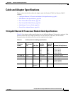
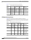
Cable and Adapter Specifications
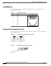
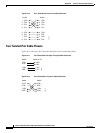
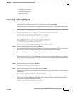
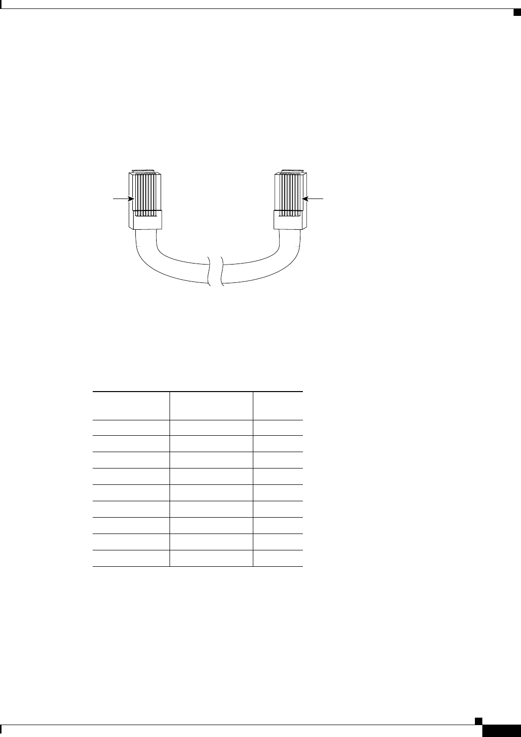
Identifying a Crossover Cable
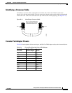
To identify a crossover cable, compare the two modular ends of the cable. Hold the cable ends
side-by-side, with the tab at the back. The wire connected to the pin on the outside of the left plug should
be the same color as the wire connected to the pin on the outside of the right plug. (See
Figure B-13.)
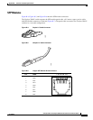
Figure B-13 Identifying a Crossover Cable
Pin 1
H10632
Pin 8
Pin 1 on one connector and
pin 8 on the other connector
should be the same color.
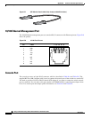
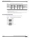
Console Port Adapter Pinouts
Table B-4 lists the pinouts for the console port, the RJ-45-to-DB-9 adapter cable, and the console device.
Ta b l e B-4 Console Port Signaling Using a DB-9 Adapter
Switch Console
Port (DTE)
RJ-45-to-DB-9
Terminal Adapter
Console
Device
Signal DB-9 Pin Signal
RTS 8 CTS
DTR 6 DSR
TxD 2 RxD
GND 5 GND
GND 5 GND
RxD 3 TxD
DSR 4 DTR
CTS 7 RTS