


1-13
Catalyst 3750-E and Catalyst 3560-E Switch Hardware Installation Guide
OL-9774-03
Chapter 1 Product Overview
Rear Panel Description
Rear Panel Description
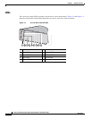
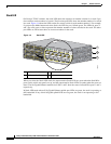
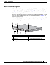
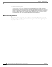
The 24- and 48-port switch rear panels have a ground location, an RPS 2300 connector, an RJ-45 console
port, a power-supply module, a fan module, an RJ-45 10/100 management port, and two StackWise
connectors (only Catalyst
3750-E switches), as shown in Figure 1-7, and described on the following
pages. Figure 1-7 shows the Catalyst 3750E-48 PoE switch as an example. All the 24- and 48-port
switches have similar components.
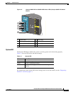
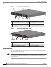
The Catalyst 3560E-12D switch rear panel has two power-supply modules, four fan modules, an RJ-45
console port, an RJ-45 10/100 management port, and a ground location, as shown in
Figure 1-8, and
described on the following pages.
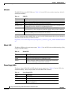
The Catalyst 3560E-12SD switch rear panel has two power-supply modules, two fan modules, an RJ-45
console port, an RJ-45 10/100 management port, and a ground location, as shown in
Figure 1-9, and
described on the following pages.
Figure 1-7 24- and 48-Port Switch Rear Panel
158107
AC OK PS O
K
100-240 V
10-5 A
50-60 HZ
STACK 1 STACK 2
CONSOLE
SERIAL
10/100TX
21 3
67 5
4
8
1 Ground location 5 Power-supply module
2 RPS 2300 connector (shown with cover) 6 Fan module
3 Console port 7 Ethernet management port and LED
4 Power-supply LEDs 8 StackWise ports
1. Only Catalyst 3750-E switches.
1