


2-8
Catalyst 3750-E and Catalyst 3560-E Switch Hardware Installation Guide
OL-9774-03
Chapter 2 Switch Installation
Planning a Switch Stack (Catalyst 3750-E Switches)
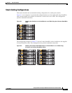
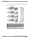
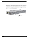
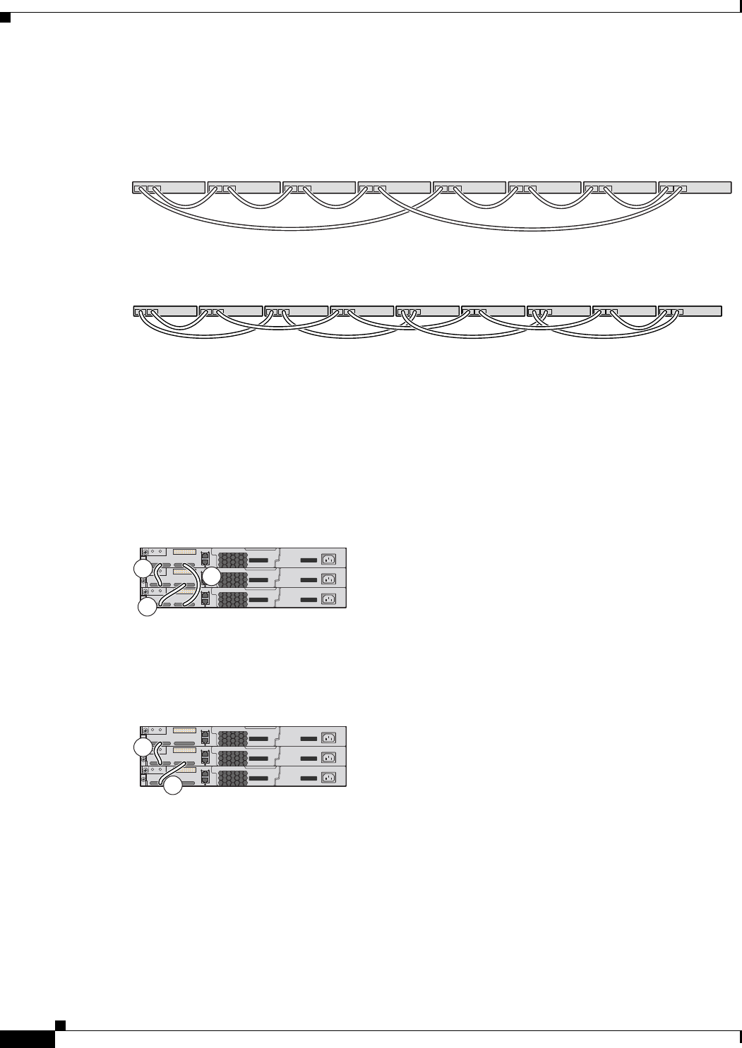
Figure 2-3 and Figure 2-4 are examples of recommended configurations when the switches are rack- or
wall-mounted side-by-side. Use the 1-meter and the 3-meter StackWise cables to connect the switches.
These configuration provide redundant connections.
Figure 2-3 Stacking up to Eight Switches in a Side-by-Side Mounting Configuration
86825
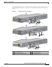
Figure 2-4 Stacking Nine Switches in a Side-by-Side Mounting Configuration
90532
Stack Bandwidth and Partitioning Examples
This section provides examples of stack bandwidth and possible stack partitioning.
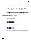
Figure 2-5 shows an example of a stack of Catalyst 3750-E switches that provides full bandwidth and
redundant StackWise cable connections.
Figure 2-5 Example of a Stack with Full Bandwidth Connections
158108
A
B
C
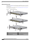
Figure 2-6 shows an example of a stack of Catalyst 3750-E switches with incomplete StackWise cabling
connections. This stack provides only half bandwidth and does not have redundant connections.
Figure 2-6 Example of a Stack with Half Bandwidth Connections
158109
A
B
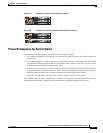
Figure 2-7 and Figure 2-8 show examples of stacks of Catalyst 3750-E switches with failover conditions.
In Figure 2-7, the StackWise cable is bad in link B; therefore, this stack provides only half bandwidth
and does not have redundant connections. In Figure 2-8, link B is bad; therefore, this stack partitions into
two stacks, and switch 1 and switch 3 are stack masters.